Acer ARMC_3P User Manual - Page 23
Placing the ARMC/3P into the Server
 |
View all Acer ARMC_3P manuals
Add to My Manuals
Save this manual to your list of manuals |
Page 23 highlights
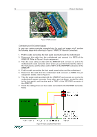
CHAPTER 2: INSTALLATION 11 Placing the ARMC/3P into the Server Open the Server In order to install the ARMC/3P you need to open the host system. Detach the host from its power cable and follow the instructions of your system documentation. Plugging an ARMC/3P into a PCI Slot ARMC/3P PCI Place the ARMC/3P into a free PCI slot. You may use any PCI slot (33 or 66 MHz, 32 or 64 Bit, PCI-X). Figure 12 Mounting the ARMC/3P into a PCI Slot Connecting Power and Reset Cables The ARMC/3P offers the possibility to remotely control both the power and the reset functions of the host system. In order to support it, there is additional cabling necessary. The preferred way for this cabling are the interfaces offered by IPMI. However, if your host does not support IPMI you may use one of the other possibilities. Connecting over IPMB This connection is used to power on or power off the system, or to perform a hard reset. You must have a motherboard that supports IPMI 1.5 or higher and has a 3 or 4 pin IPMB connector as shown in Figure 14 o Connect the 5 pin connector of the IPMB cable with the 1x5 pin IPMB connector on the ARMC/3P as shown in Figure 7. o Connect the other ending of the cable with one of the IPMB connectors (3 or 4 pin connector) on the motherboard. o Set the IPMI settings to IPMI over IPMB. o Make sure that the IPMI function is enabled on the host system. Figure 13 IPMB Cable
-
 1
1 -
2
-
3
-
4
-
5
-
6
-
7
-
8
-
9
-
10
-
11
-
12
-
13
-
14
-
15
-
16
-
17
-
 18
18 -
 19
19 -
 20
20 -
 21
21 -
 22
22 -
 23
23 -
 24
24 -
 25
25 -
 26
26 -
 27
27 -
 28
28 -
29
-
30
-
31
-
32
-
33
-
34
-
35
-
36
-
37
-
38
-
39
-
40
-
41
-
42
-
43
-
44
-
45
-
46
-
47
-
48
-
49
-
50
-
51
-
52
-
53
-
54
-
55
-
56
-
57
-
58
-
59
-
60
-
61
-
62
-
63
-
64
-
65
-
66
-
67
-
68
-
69
-
70
-
71
-
72
-
73
-
74
-
75
-
76
-
77
-
78
-
79
-
80
-
81
-
82
-
83
-
84
-
85
-
86
-
87
-
88
-
89
-
90
-
91
-
92
-
93
-
94
-
95
-
96
-
97
-
98
-
99
-
100
-
101
-
102
-
103
-
104
-
105
-
106
-
107
-
108
-
109
-
110
-
111
-
112
-
113
-
114
-
115
-
116
-
117
-
118
-
119
-
120
-
121
-
122
-
123
-
124
-
125
-
126
-
127
-
128
-
129
-
130
-
131
-
132
-
133
-
134
-
135
-
136
 |
 |
