Acer ARMC_3P User Manual - Page 20
Serial Interface, USB Plug, Video/USB System Interface, 100 Mpbs Ethernet Adaptor, External Power
 |
View all Acer ARMC_3P manuals
Add to My Manuals
Save this manual to your list of manuals |
Page 20 highlights
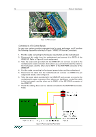
8 PRODUCT USER GUIDE Serial Interface An optional external modem may be connected to the ARMC/3P using this connector. The connector is compliant to the RS 232 serial line standard with hardware handshake. Every off-the-shelf modem can be connected to the ARMC/3P via the RS 232 interface. For details on configuring and using the serial interface please see Chapter 5: Serial Port. USB Plug Use this connector to connect the ARMC/3P with the host's USB interface. Video/USB System Interface This interface combines both the USB and the Video input connector of the ARMC/3P. Please connect the supplied system cable to the connector, only. 10/100 Mpbs Ethernet Adaptor UTP Cat 3 or 5 cables can be connected to the ARMC/3P using a standard RJ45 jack. Refer to Appendix F for the details of the pin assignment for the RJ45 connector. External Power Option To allow the ARMC/3P to operate independently from the server system, An external power supply must be connected to the ARMC/3P. Please see Chapter 2: Connecting Optional External Power Supply for further details. Power using ATX Power Cable Adaptor The 20-pole or 24-pole ATX Power Cable Adaptor has to be connected to the ARMC/3P and between the motherboard and the host power supply for the internal powering of the ARMC/3P. Please see Chapter 2: Connecting Power using ATX Power Cable Adaptor for further details. ATX Power Reset Additional cables are required in order to enable the remote reset and the remote power functions of the ARMC/3P. The reset/power switch has the pin assignment as shown in Figure 9. Please see Chapter 2: Connecting to ATX Control Signals for further details.
-
 1
1 -
2
-
3
-
4
-
5
-
6
-
7
-
8
-
9
-
10
-
11
-
12
-
13
-
14
-
 15
15 -
 16
16 -
 17
17 -
 18
18 -
 19
19 -
 20
20 -
 21
21 -
 22
22 -
 23
23 -
 24
24 -
 25
25 -
26
-
27
-
28
-
29
-
30
-
31
-
32
-
33
-
34
-
35
-
36
-
37
-
38
-
39
-
40
-
41
-
42
-
43
-
44
-
45
-
46
-
47
-
48
-
49
-
50
-
51
-
52
-
53
-
54
-
55
-
56
-
57
-
58
-
59
-
60
-
61
-
62
-
63
-
64
-
65
-
66
-
67
-
68
-
69
-
70
-
71
-
72
-
73
-
74
-
75
-
76
-
77
-
78
-
79
-
80
-
81
-
82
-
83
-
84
-
85
-
86
-
87
-
88
-
89
-
90
-
91
-
92
-
93
-
94
-
95
-
96
-
97
-
98
-
99
-
100
-
101
-
102
-
103
-
104
-
105
-
106
-
107
-
108
-
109
-
110
-
111
-
112
-
113
-
114
-
115
-
116
-
117
-
118
-
119
-
120
-
121
-
122
-
123
-
124
-
125
-
126
-
127
-
128
-
129
-
130
-
131
-
132
-
133
-
134
-
135
-
136
 |
 |
