2010 Yamaha Motorsports FX Nytro MTX Owners Manual - Page 33
2010 Yamaha Motorsports FX Nytro MTX Manual

Page 33 highlights
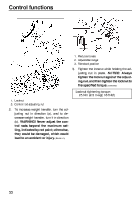
Control functions 1 2 3 1. Air valve 2. Hose connector 3. Hose connector lock lever 1. Bleed valve button TIP If the shock absorber has no air pressure, the gauge reading will be zero. 5. To increase the air pressure, operate the pump a few times. The pressure should increase slowly. If the pressure increases rapidly, check to make sure that the pump is properly connected and tightened onto the air valve. To decrease the air pressure, push the black bleed valve button. NOTICE: Do not exceed 1406 kPa (14.1 kgf/cm², 200 psi). [ECS00980] 50 60 40 psi 30 70 20 80 10 100 90 0 Air pressure range: 246 kPa (2.5 kgf/cm², 35 psi) to 1406 kPa (14.1 kgf/cm², 200 psi) Recommended air pressure: 345 kPa (3.4 kgf/cm², 50 psi) TIP To allow pressure to escape from the pump and the shock absorber, push the button halfway down and hold it. To allow only a small amount of pressure to escape, push the button all the way down and quickly release it. 6. Push the hose connector lock lever down, and then remove the hose connector from the air valve. 1 TIP When removing the connector, the sound of air escaping may be heard, but this is from the pump hose, not the shock absorber. 7. Install the air valve cap. TIP 1. Pressure gauge (low-pressure meter) If the shock absorber bottoms too easily or rolls too much during cornering, increase the air pressure by 34 kPa (0.3 kgf/cm², 5 psi). If the shock absorber is too firm and you want a more compliant ride, decrease the air pressure by 34 kPa (0.3 kgf/cm², 5 psi). 27
-
 1
1 -
2
-
3
-
4
-
5
-
6
-
7
-
8
-
9
-
10
-
11
-
12
-
13
-
14
-
15
-
16
-
17
-
18
-
19
-
20
-
21
-
22
-
23
-
24
-
25
-
26
-
27
-
 28
28 -
 29
29 -
 30
30 -
 31
31 -
 32
32 -
 33
33 -
 34
34 -
 35
35 -
 36
36 -
 37
37 -
 38
38 -
39
-
40
-
41
-
42
-
43
-
44
-
45
-
46
-
47
-
48
-
49
-
50
-
51
-
52
-
53
-
54
-
55
-
56
-
57
-
58
-
59
-
60
-
61
-
62
-
63
-
64
-
65
-
66
-
67
-
68
-
69
-
70
-
71
-
72
-
73
-
74
-
75
-
76
-
77
-
78
-
79
-
80
-
81
-
82
-
83
-
84
-
85
-
86
-
87
-
88
-
89
-
90
-
91
-
92
-
93
-
94
-
95
-
96
 |
 |
