2009 Yamaha Motorsports VMAX Owners Manual - Page 84
2009 Yamaha Motorsports VMAX Manual

Page 84 highlights
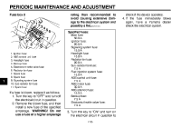
PERIODIC MAINTENANCE AND ADJUSTMENT 1 1 2 3 4 5 6 7 8 9 1. Heat insulator 2. Battery charger will damage the battery. If you do not have access to a constant-voltage battery charger, have a Yamaha dealer charge your battery. original position. NOTICE: Make sure that the heat insulator is in its original position and it is properly folded.[ECA16550] 2 To store the battery 1. If the vehicle will not be used for more than one month, remove the battery, fully charge it, and then place it in a cool, dry place. NOTICE: When removing the battery, be sure the key is turned to "OFF", then disconnect the negative lead before disconnecting the positive lead.[ECA16302] 2. If the battery will be stored for more than two months, check it at least once a month and fully charge it if necessary. To install the battery TIP Be sure the battery is fully charged. 1. Place the battery in its compartment. 2. Fold the heat insulator back to its 7-33 1 8. Pull the battery out of its compartment. To charge the battery Have a Yamaha dealer charge the battery as soon as possible if it seems to have discharged. Keep in mind that the battery tends to discharge more quickly if the vehicle is equipped with optional electrical accessories. ECA16520 1. Heat insulator NOTICE To charge a VRLA (Valve Regulated Lead Acid) battery, a special (constant-voltage) battery charger is required. Using a conventional battery 3. Install the rubber damper. 4. Install the battery cover (together with the ECU) by installing the bolts. 5. Connect coupler A. 6. Install the main fuse (together with the holding band) on its holder. 7. Connect the positive battery lead first, then connect the negative battery lead by installing their bolt.
-
 1
1 -
2
-
3
-
4
-
5
-
6
-
7
-
8
-
9
-
10
-
11
-
12
-
13
-
14
-
15
-
16
-
17
-
18
-
19
-
20
-
21
-
22
-
23
-
24
-
25
-
26
-
27
-
28
-
29
-
30
-
31
-
32
-
33
-
34
-
35
-
36
-
37
-
38
-
39
-
40
-
41
-
42
-
43
-
44
-
45
-
46
-
47
-
48
-
49
-
50
-
51
-
52
-
53
-
54
-
55
-
56
-
57
-
58
-
59
-
60
-
61
-
62
-
63
-
64
-
65
-
66
-
67
-
68
-
69
-
70
-
71
-
72
-
73
-
74
-
75
-
76
-
77
-
78
-
 79
79 -
 80
80 -
 81
81 -
 82
82 -
 83
83 -
 84
84 -
 85
85 -
 86
86 -
 87
87 -
 88
88 -
 89
89 -
90
-
91
-
92
-
93
-
94
-
95
-
96
-
97
-
98
-
99
-
100
-
101
-
102
-
103
-
104
-
105
-
106
-
107
-
108
-
109
-
110
-
111
-
112
-
113
-
114
 |
 |
