2006 Yamaha Motorsports Apex GT Owners Manual - Page 75
2006 Yamaha Motorsports Apex GT Manual

Page 75 highlights
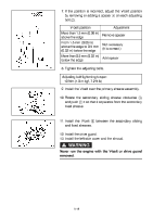
1. Remove the shroud and the left side cover. (See pages 8-5-8-7 for removal procedures.) 2. Remove the drive guard. 3. Rotate the secondary sliding sheave clockwise 1 and push 2 it so that it separates from the secondary fixed sheave. 4. Pull 3 the V-belt up over the secondary fixed sheave. 5. Remove the V-belt from the secondary sheave assembly and primary sheave assembly. 6. Temporarily install the new V-belt on the secondary sheave assembly only, and then measure the V-belt position. Do not force the V-belt between the sheaves; the secondary sliding and fixed sheaves must touch each other. Standard V-belt position a: From 1.5 mm (0.06 in) above the edge of the secondary sheave assembly to 0.5 mm (0.02 in) below the edge. 8-17
-
 1
1 -
2
-
3
-
4
-
5
-
6
-
7
-
8
-
9
-
10
-
11
-
12
-
13
-
14
-
15
-
16
-
17
-
18
-
19
-
20
-
21
-
22
-
23
-
24
-
25
-
26
-
27
-
28
-
29
-
30
-
31
-
32
-
33
-
34
-
35
-
36
-
37
-
38
-
39
-
40
-
41
-
42
-
43
-
44
-
45
-
46
-
47
-
48
-
49
-
50
-
51
-
52
-
53
-
54
-
55
-
56
-
57
-
58
-
59
-
60
-
61
-
62
-
63
-
64
-
65
-
66
-
67
-
68
-
69
-
 70
70 -
 71
71 -
 72
72 -
 73
73 -
 74
74 -
 75
75 -
 76
76 -
 77
77 -
 78
78 -
 79
79 -
 80
80 -
81
-
82
-
83
-
84
-
85
-
86
-
87
-
88
-
89
-
90
-
91
-
92
-
93
-
94
-
95
-
96
-
97
-
98
-
99
-
100
-
101
-
102
-
103
-
104
-
105
-
106
 |
 |

8-17
1. Remove the shroud and the left side cover. (See
pages 8-5–8-7 for removal procedures.)
2. Remove the drive guard.
3. Rotate the secondary sliding sheave clockwise
1
and push
2
it so that it separates from the secondary
fixed sheave.
4. Pull
3
the V-belt up over the secondary fixed sheave.
5. Remove the V-belt from the secondary sheave
assembly and primary sheave assembly.
6. Temporarily install the new V-belt on the secondary
sheave assembly only, and then measure the V-belt
position. Do not force the V-belt between the
sheaves; the secondary sliding and fixed sheaves
must touch each other.
Standard V-belt position
a
:
From 1.5 mm (0.06 in) above the edge of the second-
ary sheave assembly to 0.5 mm (0.02 in) below the
edge.