Maytag MER5750BAQ Installation Manual
Maytag MER5750BAQ - Electric Range Manual
 |
View all Maytag MER5750BAQ manuals
Add to My Manuals
Save this manual to your list of manuals |
Maytag MER5750BAQ manual content summary:
- Maytag MER5750BAQ | Installation Manual - Page 1
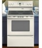
WITH THE APPLIANCE MANUAl Electric 30-inch Wide Free-stand" e PLEASE KEEP THIS MANUAL FOR FUTURE REFERENCE THE MANUAL IS INTENDED TO ASSIST IN THE INITIAL INSTALLATION AND ADJUSTMENTS OF THE RANGE. Only qualified personnel should install or service this range. Read "Safety Instructions" in Use - Maytag MER5750BAQ | Installation Manual - Page 2
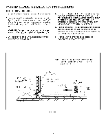
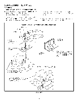
located above the surface units should be avoided. If cabinet storage is to be provided, the risk can be reduced by installing a range hood that projects horizontally a minimum of 5 inches (13 cm) beyond the bottom of the cabinets. FIGURE 1 1, 2, 3 - COMBUSTIBLE BUILDING WALLS. 4 - COMBUSTIBLE WALL - Maytag MER5750BAQ | Installation Manual - Page 3
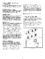
of range tip-over exists if the appliance is not installed in accordance with the provided installation instructions. The proper use of this device minimizes the risk of TIP-OVER. tn using this device the consumer must still observe the safety precautions as stated in the USE and CARE MANUAL and - Maytag MER5750BAQ | Installation Manual - Page 4
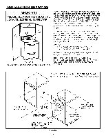
oven rack. tf an adjustment is required pull the range forward, tip the range and rotate the leveling feet as required. E. To check the range bracket slot. F. Proceed with the remainder of the installation instructions provided with the range. SCREWS ENTER WOOD OR METAL. WALL PLATE ART_ 9215-117 - Maytag MER5750BAQ | Installation Manual - Page 5
models. Just plug into the range outlet. On models not provided with a service cord, connection to the power supply is necessary. REMEMBER - only a 4-conductor cord is to be used on new branch-circuit installations (1996 NEC), mobile homes, recreational vehicles, or in an area where local codes - Maytag MER5750BAQ | Installation Manual - Page 6
Installation 1. Insure that the copper ground strap IS CONNECTED between the middle post of the main terminal connection block and the range chassis. 2. The middle wire of the service cord or ground lead of 3-wire conduit MUST connect to the neutral (middle) post of the main terminal block. The - Maytag MER5750BAQ | Installation Manual - Page 7
plate. Conversion From 3-Wire To 4-Wire Service (Free-standing Model With 3-Wire Service Cord Attached), Disconnect range from power. Remove the access cover on back of range and remove the 3-wire service cord from the main terminal block. Follow instructions as outlined in figure 7 to connect the - Maytag MER5750BAQ | Installation Manual - Page 8
individual de 30 pulg 76.2 cm) de ancho CONSERVE ESTE MANUAL PARA REFERENCIA FUTURA EL MANUAL TIENE LA FINALIDAD DE AYUDARLE EN LA INSTALACION Y AJUSTES Titulo 24 CFR, Parte 3280 (anteriormente Federal Standard for Mobile Home Construction and Safety, Titulo 24 HUD, Parte 280)) o, cuando - Maytag MER5750BAQ | Installation Manual - Page 9
ADYACENTE. "A" = 30" (76.2 CM) - 31" (78.7 CM) EN CANADA "B" = 7" (17.8 CM) - 7 1/2" (19.1 CM) EN CANADA 36" (91.5 CM) ALTURA A LA PARTE SUPERIOR DEL MOSTRADOR _ 5 3/4" (14.6 CM J -""A" / J ABERTURADSEL ARRtBA Y DE ABAJO _" PROVEA UN TOMACORRIENTE DE 120/208, 120/240 VOLTIOS POR CORDON - Maytag MER5750BAQ | Installation Manual - Page 10
reduce el riesgo de LADEO. AI usar este dispositivo el consumidor aun debe acatar las precauciones de seguridad que se dictan en el MANUAL DE USO Y CUIDADO y debe evitar utilizar las puertas del horno come banquillo. Las instrucciones de instalacion se proporcionan para madera y cemento tanto en - Maytag MER5750BAQ | Installation Manual - Page 11
segQn sea necesario. E. Para revisar que el soporte antiladeo este instalado correctamente en la estufa: Use una linterna y vea debajo de la parte inferior de la estufa para comprobar que una de las patas niveladoras posteriores este asegurada a la ranura del soporte. F. ContinQe con el resto - Maytag MER5750BAQ | Installation Manual - Page 12
, asegQrese de que esten bien aseguradas las conexiones electricas y coloque las cubiertas de nuevo. Quite la cubierta de acceso del bloque terminal de la parte posterior de la estufa. (Vea la figura 5). CONEXIONES DE LA ESTUFA (en Canada) Este modelo se embarc6 directamente de fabrica con el cord6n - Maytag MER5750BAQ | Installation Manual - Page 13
CONEXION DE LA ESTUFA FIGURA 6 INSTALACION DEL CORDON DE SERVICIO DE 3 CABLES O DEL CONDUCTOR Verifi.que que la tira de conexi6n a tierra de cobre ESTE CONECTADA entre el poste medio del bloque de conexi6n del terminal principal y del bastidor de la estufa. terminal principal. Los otros dos - Maytag MER5750BAQ | Installation Manual - Page 14
Modelo individual con cordon sujeto de servicio de 3 cables) Desconecte la estufa de la energia electrica. Quite la cubierta de acceso en la parte posterior de la estufa y quite el cord6n de servicio de 3 cables del bloque del terminal principal. Siga las instrucciones a continuacion segQn se indica - Maytag MER5750BAQ | Installation Manual - Page 15
INSTRUCTIONS AVEC L'APPAREIL MAN U EL D E M VEUILLEZ CONSERVER CE MANUEL POUR R#FI_RENCE ULTI_RIEURE CE MANUEL EST DESTINE A FACILITER LA MISE EN SERVICE ET LE REGLAGE INITIAUX DE LA CUISINIERE. La mise en service les codes de a des armoires pouvant supporter une temperature inferieure a - Maytag MER5750BAQ | Installation Manual - Page 16
amovible peut 6tre directement contre (0 cm/po) les parois 1,2, 3 m6me si celles-ci sont en materiau combustible. REMARQUE : DANS LE CAS D'UNE MISE EN SERVICE AU CANADA, UNE CUISINIERE AMOVIBLE NE DOlT PAS ETRE PLACEE .& MOINS DE 12 MM DE TOUTE SURFACE ADJACENTE. "A" = 76,2 CM (30 PO - 78,7 (31 - Maytag MER5750BAQ | Installation Manual - Page 17
cuisiniere risque de basculer si elle n'est pas mise en place conformement aux instructions fournies. Si le support est utilise correctement, il reduit le risque que la cuisiniere ne BASCULE. M6me si le support est utilise correctement, le consommateur doit observer les precautions indiquees dans le - Maytag MER5750BAQ | Installation Manual - Page 18
des pieds arriere de mise niveau est bien insere dans la fente du support. F. Finir la mise en service de la cuisiniere tel qu'indique dans les instructions fournies avec la cuisiniere. REMARQUE : UTILISER AU MOINS 2 VIS POUR LA FIXATION DU SUPPORT AU MUR OU AU PLANCHER LES VlS D OIV, ENT DANS LE - Maytag MER5750BAQ | Installation Manual - Page 19
service, la cuisiniere doit _tre installee conformement aux normes NEC ANSI/NFPA n ° 70-edition la plus recente du code service, la cuisiniere doit _tre installee conformement aux normes ACN STD.C22.1 de I'edition la plus recente du code codes si les codes Iocaux modele codes codes codes modeles modeles - Maytag MER5750BAQ | Installation Manual - Page 20
borne neutre (celle du milieu) du bornier. Les deux autres ills du cordon sont 3. Placer la retenue mecanique a bride sur le dessus de la plaque support de gaine tel qu'indique et serrer la bride sur le cordon d'alimentation ou la gaine. INSTALLATION ACCEPTABLE - FICHE A TROIS FILS BLANC -- NOIR - Maytag MER5750BAQ | Installation Manual - Page 21
MAISONS MOBILES OU SI LES CODES L'EXIGENT) 1. La barrette a bride sur le dessus de la plaque support de gaine tel qu'indique et la serrer FILS .&. UNE INSTALLATION 4 FILS (Modeles amovibles avec cordon d'alimentation en place ills du bornier. Suivre les instructions donnees a la figure 7 pour
-
 1
1 -
 2
2 -
 3
3 -
 4
4 -
 5
5 -
 6
6 -
 7
7 -
8
-
9
-
10
-
11
-
12
-
13
-
14
-
15
-
16
-
17
-
18
-
19
-
20
-
21
 |
 |
INSTALLER:
LEAVE
THESE
INSTRUCTIONS
WITH
THE APPLIANCE
ON
MANUAl
IN
Electric
30-inch
Wide
Free-stand"
PLEASE
KEEP
THIS
MANUAL
e
FOR
FUTURE
REFERENCE
THE MANUAL
IS INTENDED
TO ASSIST
IN THE INITIAL
INSTALLATION
AND ADJUSTMENTS
OF
THE RANGE.
Only
qualified
personnel
should
install or service
this
range.
Read
"Safety
Instructions"
in Use
&
Care book before
using
range.
Improper
installation,
adjustment,
alteration,
service,
maintenance
or
use of range
can
result
in serious
injury
or property
damage.
CAUTION:
This range
has been designed
in
accordance
with the requirements
of various
safety
agencies
and complies
with the maximum
allowable
wood
cabinet
temperatures
of
194°F.
tf this
range is
installed
with
cabinets
that have a lower working
temperature
than 194°F,
discoloration,
delamination
or melting
may occur.
ENGLISH
0
PP.
1-7
ESPANOL
0
pag.
8-14
FRAN(_AIS
i$
p. 15-21
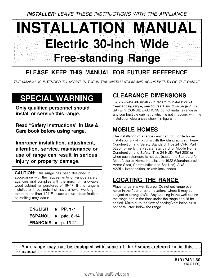
CLEARANCE
DIMENSIONS
For complete
information
in regard to installation of
freestanding
range, see figures
1 and 2 on page 2. For
SAFETY
CONSIDERATIONS
do not install a range in
any combustible
cabinetry which is not in accord with the
installation clearances
shown in figure 1.
MOBILE
HOMES
The installation of a range designed for mobile home
installation must conform with the Manufactured
Home
Construction
and Safety Standard, Title 24 CFR, Part
3280 (formerly
the Federal Standard for Mobile Home
Construction
and Safety, Title 24 HUD, Part 280) or,
when such standard
is not applicable,
the Standard for
Manufactured
Home Installations
1982 (Manufactured
Home Sites, Communities
and Set-Ups), ANSI
A225.1-1atest edition, or with local codes.
LOCATING
THE
RANGE
Place range in a well lit area. Do not set range over
holes in the floor or other locations where
it may be
subject to strong drafts. Any opening
in the wall behind
the range and in the floor under the range should be
sealed.
Make sure the flow of cooling/ventilation
air is
not obstructed
below the range.
8101 P431-60
(10-01-00)