Stihl HS 87 Instruction Manual - Page 19
WARNING, Refueling, Closing
 |
View all Stihl HS 87 manuals
Add to My Manuals
Save this manual to your list of manuals |
Page 19 highlights
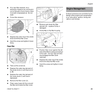
3 4 0000-GXX-6425-A0 5 N Turn the cap to the open position (3) only after the contents of the tank are no longer under pressure. In the open position, the exterior positioning mark (4) on the cap will line up with the "unlocked" symbol (5) on the fuel tank housing. N Remove the fuel filler cap. WARNING Never remove the cap by turning it directly to the open position. First allow the power tool to cool adequately and then release any residual pressure at the vent position (2). Never attempt to remove the cap while the engine is still hot or running. Refueling Take care not to spill fuel while fueling and do not overfill the tank - leave approximately 1/2" (13 mm) air space. Closing WARNING An improperly tightened fuel filler cap can loosen or come off and spill quantities of fuel. To reduce the risk of fuel spillage and fire from an improperly installed fuel cap, correctly position and tighten the cap in the fuel tank opening: 1 2 N Raise the grip on the top of the cap until it is upright at a 90° angle. Insert the cap in the fuel tank opening with the exterior positioning mark (1) lined up with the "unlocked" symbol (2) on the fuel tank housing. 4 1 3 N Using the grip, press the cap down firmly while turning it clockwise to the closed position (approximately 1/4 turn). In the closed position, the interior (4) and exterior (1) positioning marks will align with the "locked" symbol (3) on the fuel tank housing. N Fold the grip flush with the top of the cap and check for tightness. 0000-GXX-6427-A0 0000-GXX-6426-A0 English WARNING If the grip does not lie completely flush with the cap or the detent on the grip does not fit in the corresponding recess in the tank opening, or if the cap is loose, the cap is not properly seated and you must repeat the above steps. Also refer to the procedure below for returning the base of the cap to the proper starting position for installation. HS 87 R, HS 87 T 17
-
 1
1 -
2
-
3
-
4
-
5
-
6
-
7
-
8
-
9
-
10
-
11
-
12
-
13
-
 14
14 -
 15
15 -
 16
16 -
 17
17 -
 18
18 -
 19
19 -
 20
20 -
 21
21 -
 22
22 -
 23
23 -
 24
24 -
25
-
26
-
27
-
28
-
29
-
30
-
31
-
32
-
33
-
34
-
35
-
36
-
37
-
38
-
39
-
40
-
41
-
42
-
43
-
44
-
45
-
46
-
47
-
48
-
49
-
50
-
51
-
52
-
53
-
54
-
55
-
56
-
57
-
58
-
59
-
60
-
61
-
62
-
63
-
64
-
65
-
66
-
67
-
68
-
69
-
70
-
71
-
72
-
73
-
74
-
75
-
76
-
77
-
78
-
79
-
80
 |
 |
