Sharp PN-L805H Operation Manual - Page 10
Part Names
 |
View all Sharp PN-L805H manuals
Add to My Manuals
Save this manual to your list of manuals |
Page 10 highlights
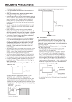
Part Names nFront view 8 8 8 8 12 3 4 75 6 7 1. Remote control sensor (See page 15.) 2. Power LED (See page 17.) 3. POWER button (See page 17.) 4. TOUCH MENU button (See page 25.) 5. USB port (for USB device) (USB 2.0 compliant) To use, remove the seal and connect the USB cable on the back of the tray ("32") to the computer. (See page 13.) 6. Tray 7. Speakers 8. Handles nRear view 9 10 11 32 12 13 14 15 16 17 18 19 20 21 22 23 24 25 TIPS • It is convenient to use the terminals for separate purposes; for example, using the terminal on the bottom of the monitor to connect a fixed computer and using the terminal on the side of the monitor to connect a mobile computer. Caution • Consult your SHARP dealer for attachment/detachment of optional parts. 9. Vents 10. Optional attachment section This section is used to connect optional 26 hardware for function expansion. Offering this attachment location is not a guarantee that 27 future compatible hardware attachments will be released. 28 11. Expansion slot This section is used to connect optional 29 hardware for function expansion. Offering this attachment location is not a guarantee that 30 future compatible hardware attachments will be 31 released. 12. Main power switch (See page 17.) 13. AC input terminal (See page 14.) 14. External speaker terminals (See page 13.) 15. Audio output terminal (See page 13.) 16. LAN terminal (See page 13.) 17. Optional terminal This terminal is provided for possible future (optional) function expansion. Offering of this terminal is not a guarantee that future expanded functionality will be released. 18. RS-232C input terminal (See page 13.) 19. Touch pen adapter port (See page 19.) 20. USB port (See page 13.) 21. USB 1 port (for touch panel) (See page 13.) 22. DisplayPort output terminal (See page 13.) 23. HDMI 1 input terminal (See page 12.) 24. DisplayPort 1 input terminal (See page 12.) 25. Audio input terminal (See page 12.) 26. Terminal for firmware updating Normally not used. 27. USB 2 port (for touch panel) (See page 13.) 28. D-sub input terminal (See page 12.) 29. DisplayPort 2 input terminal (See page 12.) 30. HDMI 2 input terminal (See page 12.) 31. HDMI 3 input terminal (See page 12.) 32. USB cable (See page 13.) E 10
-
 1
1 -
2
-
3
-
4
-
 5
5 -
 6
6 -
 7
7 -
 8
8 -
 9
9 -
 10
10 -
 11
11 -
 12
12 -
 13
13 -
 14
14 -
 15
15 -
16
-
17
-
18
-
19
-
20
-
21
-
22
-
23
-
24
-
25
-
26
-
27
-
28
-
29
-
30
-
31
-
32
-
33
-
34
-
35
-
36
-
37
-
38
-
39
-
40
-
41
-
42
-
43
-
44
-
45
-
46
-
47
-
48
-
49
-
50
-
51
-
52
-
53
-
54
-
55
-
56
-
57
-
58
-
59
-
60
-
61
-
62
-
63
-
64
-
65
-
66
-
67
-
68
-
69
-
70
-
71
-
72
-
73
 |
 |
