Sharp FO IS125N Service Manual - Page 104
Hardware controlled protection function, Device, Protective action, Circuit description, Purpose
 |
UPC - 074000034372
View all Sharp FO IS125N manuals
Add to My Manuals
Save this manual to your list of manuals |
Page 104 highlights
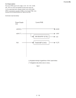
FO-IS125N 2.2.3 Hardware controlled protection function Device Heater lamp (fusing device) Laser (LSU) Protective action Circuit description Purpose 1 The heater lamp is The circuit forcibly turns off Avoiding the abnormally forcibly turned off (resets) the control signal of the high temperature of the when the temperature heater lamp when the thermistor fusing device. of the fusing device value reaches 238 ± 6 °C. To turn (thermistor value) on the heater lamp again, it is nec- exceeds the upper essary to reset all system or limit. power down once. In other words, once the protective action is per- formed, the protection is not can- celed automatically even if the temperature detected by the ther- mistor decreases. 1 When the cover is Equipped with a regulator circuit Avoiding the exposure to open, the power sup- for producing the laser system laser beam. ply to the laser system power (+5 V) supplied to the LSU circuits is shut off. from +24 V power supply inter- rupted by the interlock. 3 The sampling of S/H Equipped with a circuit for Avoiding abnormally high signal is disabled enabling output of the S/H signal output of the laser. unless the VIDEO sig- when the VIDEO signal is nal is active (laser on). received. Status to be activated The protection is activated when F/W is out of control, the microcomputer ADC is defective, or other abnormality occurred. Normally, the heater lamp is turned on/off by monitoring the temperature using F/W. Malfunction due to the digital system circuit failure. When F/W under development is defective or runs out of control, the protection is activated. Normally, each signal is controlled following the sequence by F/W. A fuse is installed in the following power supply lines: Optical unit (LSU) laser, Main motor, Pickup motor 5 - 13
-
 1
1 -
2
-
3
-
4
-
5
-
6
-
7
-
8
-
9
-
10
-
11
-
12
-
13
-
14
-
15
-
16
-
17
-
18
-
19
-
20
-
21
-
22
-
23
-
24
-
25
-
26
-
27
-
28
-
29
-
30
-
31
-
32
-
33
-
34
-
35
-
36
-
37
-
38
-
39
-
40
-
41
-
42
-
43
-
44
-
45
-
46
-
47
-
48
-
49
-
50
-
51
-
52
-
53
-
54
-
55
-
56
-
57
-
58
-
59
-
60
-
61
-
62
-
63
-
64
-
65
-
66
-
67
-
68
-
69
-
70
-
71
-
72
-
73
-
74
-
75
-
76
-
77
-
78
-
79
-
80
-
81
-
82
-
83
-
84
-
85
-
86
-
87
-
88
-
89
-
90
-
91
-
92
-
93
-
94
-
95
-
96
-
97
-
98
-
 99
99 -
 100
100 -
 101
101 -
 102
102 -
 103
103 -
 104
104 -
 105
105 -
 106
106 -
 107
107 -
 108
108 -
 109
109 -
110
-
111
-
112
-
113
-
114
-
115
-
116
-
117
-
118
-
119
-
120
-
121
-
122
-
123
-
124
-
125
-
126
-
127
-
128
-
129
-
130
-
131
-
132
-
133
-
134
-
135
-
136
-
137
-
138
-
139
-
140
-
141
-
142
-
143
-
144
-
145
-
146
-
147
-
148
-
149
-
150
-
151
-
152
-
153
-
154
-
155
-
156
-
157
-
158
-
159
-
160
-
161
-
162
-
163
-
164
-
165
-
166
-
167
-
168
-
169
-
170
-
171
-
172
-
173
-
174
-
175
-
176
-
177
-
178
 |
 |
