Panasonic WU-216MF2U9 - Technical Data Manual - Page 63
Refrigerant tube port, Tightening torque for each cap, Cap tightening torque
 |
View all Panasonic WU-216MF2U9 manuals
Add to My Manuals
Save this manual to your list of manuals |
Page 63 highlights
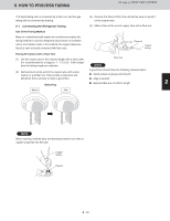
5. HOW TO INSTALL THE OUTDOOR UNIT Design of 3WAY VRF SYSTEM Refrigerant tube port Tubing cover Use caulking, putty, or a similar material to fill any gaps at the refrigerant tube port ( ) in order to prevent rainwater, dust or foreign substances from entering the unit. * Perform this work even if the tubing is routed out in a downward direction. Tighten each cap as specified below. Tightening torque for each cap Tubing routed out Cap tightening torque Type 72 Type 96 Type 120 Type 144 through the front side Bottom plate (6 Ton) (8 Ton) (10 Ton) (12 Ton) Service port cap lbs · inch N · m {kgf · cm} 90-100 10-12 {100-120} The liquid tube valve Valve cap Flare nut lbs · inch N · m {kgf · cm} lbs · inch N · m 120-170 14-20 {140-200} 300-360 34-42 190-240 22-28 {220-280} 430-610 49-61 For type 96 Tubing routed out through the bottom Unit: in. (mm) 1 {kgf · cm} {340-420} {490-610} Service port cap The discharge Valve cap lbs · inch N · m {kgf · cm} lbs · inch N · m 90-100 10-20 {100-200} 420-530 48-60 90-100 10-20 {100-200} 170-220 20-25 Valve cap width 35/64 (14) Service port cap width 43/64 (17) Flare nut ø1/4 (ø6.35) Service port cap width 43/64 (17) tube valve {kgf · cm} lbs · inch {480-600} 590-710 {200-250} - Balance tube Valve cap width 43/64 (17) 2 Flare nut Service The suction port cap tube valve Valve cap Service port cap N · m {kgf · cm} lbs · inch N · m {kgf · cm} lbs · inch N · m {kgf · cm} lbs · inch N · m {kgf · cm} 67-81 - {680-820} - 90-100 10-12 {100-120 } 170-220 20-25 {200-250} 90-100 10-12 {100-120 } Service port cap width 43/64 (17) Service port cap width 43/64 (17) Valve cap width 3/4 (19) Flare nut ø3/8 (ø9.52) Liquid tube Valve cap DDisiscchhaargrgee width 1-3/16 (30) tube Suction tube 3 Flare nut ø5/8 (ø15.88) For type 120/144 Unit: in. (mm) The balance tube valve Valve cap Flare nut lbs · inch N · m {kgf · cm} lbs · inch N · m 170-220 20-25 {200-250} 120-160 14-18 Valve cap width 35/64 (14) Service port cap Flare nut Valve cap 4 ø1/4 (ø6.35) width 35/64 (14) {kgf · cm} {140-180} width 43/64 (17) For type 72 Unit: in. (mm) Service port cap Balance tube Valve cap width 43/64 (17) Valve cap width 35/64 (14) Service port cap width 43/64 (17) Service port cap Flare nut ø1/4 (ø6.35) Balance tube Service port cap width 43/64 (17) Valve cap width 35/64 (14) Service port cap width 43/64 (17) Valve cap Service port cap width 43/64 (17) 5 width 17/16 (27) Service port cap width 43/64 (17) Flare nut ø1/2 (ø12.7) Liquid tube Discharge tutubbee Suction tube width 43/64 (17) width 43/64 (17) 6 Valve cap width 3/4 (19) Discharge Valve cap width 1-3/16 (30) Use two adjustable wrenches, as shown in the figure, when removing the liquid tube valve flare Flare nut ø3/8 (ø9.52) Liquid tube tube Suction tube nut and the discharge tube valve flare nut. 1. Do not apply a wrench to the valve cap when Flare nut ø5/8 (ø15.88) Do not apply an adjustable wrench removing or installing the flare nuts. Doing so may damage the valve. 7 2. If the valve cap is left off for a long period of time, to the hexagonal part. refrigerant leakage will occur. Do not use two adjustable wrenches when removing or installing the balance tube flare nut. In particular, do not apply an adjustable wrench to the hexagonal part at the top of the valve. (If force is applied to this part, gas leakage will occur.) Therefore, do not leave the valve cap off. 3. Applying refrigerant oil to the flare surface can be effective in preventing gas leakage, however, be sure to use a refrigerant oil which is suitable for the refrigerant that is used in the system. 8 (This unit utilizes R410A refrigerant, and the refrigerant oil is ether oil (synthetic oil). However, hub oil (synthetic oil) can also be used.) 27 2 - 47 9
-
 1
1 -
2
-
3
-
4
-
5
-
6
-
7
-
8
-
9
-
10
-
11
-
12
-
13
-
14
-
15
-
16
-
17
-
18
-
19
-
20
-
21
-
22
-
23
-
24
-
25
-
26
-
27
-
28
-
29
-
30
-
31
-
32
-
33
-
34
-
35
-
36
-
37
-
38
-
39
-
40
-
41
-
42
-
43
-
44
-
45
-
46
-
47
-
48
-
49
-
50
-
51
-
52
-
53
-
54
-
55
-
56
-
57
-
 58
58 -
 59
59 -
 60
60 -
 61
61 -
 62
62 -
 63
63 -
 64
64 -
 65
65 -
 66
66 -
 67
67 -
 68
68 -
69
-
70
-
71
-
72
-
73
-
74
-
75
-
76
-
77
-
78
-
79
-
80
-
81
-
82
-
83
-
84
-
85
-
86
-
87
-
88
-
89
-
90
-
91
-
92
-
93
-
94
-
95
-
96
-
97
-
98
-
99
-
100
-
101
-
102
-
103
-
104
-
105
-
106
-
107
-
108
-
109
-
110
-
111
-
112
-
113
-
114
-
115
-
116
-
117
-
118
-
119
-
120
-
121
-
122
-
123
-
124
-
125
-
126
-
127
-
128
-
129
-
130
-
131
-
132
-
133
-
134
-
135
-
136
-
137
-
138
-
139
-
140
-
141
-
142
-
143
-
144
-
145
-
146
-
147
-
148
-
149
-
150
-
151
-
152
-
153
-
154
-
155
-
156
-
157
-
158
-
159
-
160
-
161
-
162
-
163
-
164
-
165
-
166
-
167
-
168
-
169
-
170
-
171
-
172
-
173
-
174
-
175
-
176
-
177
-
178
-
179
-
180
-
181
-
182
-
183
-
184
-
185
-
186
-
187
-
188
-
189
-
190
-
191
-
192
-
193
-
194
-
195
-
196
-
197
-
198
-
199
-
200
-
201
-
202
-
203
-
204
-
205
-
206
-
207
-
208
-
209
-
210
-
211
-
212
-
213
-
214
-
215
-
216
-
217
-
218
-
219
-
220
-
221
-
222
-
223
-
224
-
225
-
226
-
227
-
228
-
229
-
230
-
231
-
232
 |
 |
