Panasonic WU-216MF2U9 - Technical Data Manual - Page 17

DESIGN OF 3WAY VRF SYSTEM, Air Purging with a Vacuum Pump for Test Run Preparation

Page 17 highlights

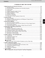
CCoonntteennttss Design of 3WAYY VVRRFF SSYYSSTTEEMM 2. DESIGN OF 3WAY VRF SYSTEM 1. Model Selection and Capacity Calculator 2-3 1-1. Operating Range ...2-3 1-2. Procedure for Selecting Models and Calculating Capacity 2-4 1-3. Tubing Length...2-5 1-4. Tubing Size ...2-8 1-5. Straight Equivalent Length of Joints 2-9 1-6. Additional Refrigerant Charge 2-9 1-7. System Limitations...2-10 1-8. Installation Standards 2-11 1-9. Check of Limit Density 2-11 1 1-10. Calculation of Actual Capacity of Indoor Unit 2-12 2. System Design ...2-17 2-1. System Example...2-17 2-2. Example of Tubing Size Selection and Refrigerant Charge Amount 2-18 2-3. Installing Distribution Joint 2-20 2 3. ELECTRICAL WIRING...2-21 3-1. General Precautions on Wiring 2-21 3-2. Recommended Wire Length and Wire Diameter for Power Supply System 2-21 3-3. Wiring System Diagram 2-22 3-4. Connecting Multiple Indoor Units to a Single Solenoid Valve Kit 2-24 3 4. SELECTING THE INSTALLATION SITE 2-29 4-1. Outdoor Unit ...2-29 4-2. Installation Standards for Outdoor Unit 2-30 4-3. Shield for Horizontal Exhaust Discharge 2-39 4-4. Installing the Outdoor Unit in Heavy Snow Areas 2-39 4-5. Precautions When Installing in Heavy Snow Areas 2-39 4 4-6. Dimensions of Wind Ducting 2-40 4-7. Dimensions of Snow Ducting 2-42 5. HOW TO INSTALL THE OUTDOOR UNIT 2-44 5-1. Transporting...2-44 5-2. Installing the Outdoor Unit 2-44 5 5-3. Routing the Tubing ...2-45 5-4. Prepare the Tubing ...2-46 5-5. Connect the Tubing ...2-46 Indoor Unit * Refer to the 3WAY VRF SYSTEM TECHNICAL DATA (TD831158) 6 6. HOW TO PROCESS TUBING 2-49 6-1. Connecting the Refrigerant Tubing 2-49 6-2. Connecting Tubing Between Indoor and Outdoor Units 2-50 6-3. Insulating the Refrigerant Tubing 2-51 6-4. Taping the Tubes ...2-51 7 6-5. Finishing the Installation 2-51 7. AIR PURGING ...2-52 Air Purging with a Vacuum Pump (for Test Run) Preparation 2-52 8 2 - 1 9

  • 1
  • 2
  • 3
  • 4
  • 5
  • 6
  • 7
  • 8
  • 9
  • 10
  • 11
  • 12
  • 13
  • 14
  • 15
  • 16
  • 17
  • 18
  • 19
  • 20
  • 21
  • 22
  • 23
  • 24
  • 25
  • 26
  • 27
  • 28
  • 29
  • 30
  • 31
  • 32
  • 33
  • 34
  • 35
  • 36
  • 37
  • 38
  • 39
  • 40
  • 41
  • 42
  • 43
  • 44
  • 45
  • 46
  • 47
  • 48
  • 49
  • 50
  • 51
  • 52
  • 53
  • 54
  • 55
  • 56
  • 57
  • 58
  • 59
  • 60
  • 61
  • 62
  • 63
  • 64
  • 65
  • 66
  • 67
  • 68
  • 69
  • 70
  • 71
  • 72
  • 73
  • 74
  • 75
  • 76
  • 77
  • 78
  • 79
  • 80
  • 81
  • 82
  • 83
  • 84
  • 85
  • 86
  • 87
  • 88
  • 89
  • 90
  • 91
  • 92
  • 93
  • 94
  • 95
  • 96
  • 97
  • 98
  • 99
  • 100
  • 101
  • 102
  • 103
  • 104
  • 105
  • 106
  • 107
  • 108
  • 109
  • 110
  • 111
  • 112
  • 113
  • 114
  • 115
  • 116
  • 117
  • 118
  • 119
  • 120
  • 121
  • 122
  • 123
  • 124
  • 125
  • 126
  • 127
  • 128
  • 129
  • 130
  • 131
  • 132
  • 133
  • 134
  • 135
  • 136
  • 137
  • 138
  • 139
  • 140
  • 141
  • 142
  • 143
  • 144
  • 145
  • 146
  • 147
  • 148
  • 149
  • 150
  • 151
  • 152
  • 153
  • 154
  • 155
  • 156
  • 157
  • 158
  • 159
  • 160
  • 161
  • 162
  • 163
  • 164
  • 165
  • 166
  • 167
  • 168
  • 169
  • 170
  • 171
  • 172
  • 173
  • 174
  • 175
  • 176
  • 177
  • 178
  • 179
  • 180
  • 181
  • 182
  • 183
  • 184
  • 185
  • 186
  • 187
  • 188
  • 189
  • 190
  • 191
  • 192
  • 193
  • 194
  • 195
  • 196
  • 197
  • 198
  • 199
  • 200
  • 201
  • 202
  • 203
  • 204
  • 205
  • 206
  • 207
  • 208
  • 209
  • 210
  • 211
  • 212
  • 213
  • 214
  • 215
  • 216
  • 217
  • 218
  • 219
  • 220
  • 221
  • 222
  • 223
  • 224
  • 225
  • 226
  • 227
  • 228
  • 229
  • 230
  • 231
  • 232

Design of 3WAY VRF SYSTEM
2
- 1
2
Contents
2. DESIGN OF 3WAY VRF SYSTEM
1. Model Selection and Capacity Calculator
..........................................................................
2-3
2-3
1-1. Operating Range
...........................................................................................................
2-4
1-2. Procedure for Selecting Models and Calculating Capacity
............................................
2-5
1-3. Tubing Length
................................................................................................................
2-8
1-4. Tubing Size
....................................................................................................................
2-9
1-5. Straight Equivalent Length of Joints
...............................................................................
2-9
1-6. Additional Refrigerant Charge
........................................................................................
2-10
1-7. System Limitations
........................................................................................................
2-11
.
8
-
1
Installation Standards
...................................................................................................
2-49
6. HOW TO PROCESS TUBING
.............................................................................................
2-50
6-2. Connecting Tubing Between Indoor and Outdoor Units
..............................................
2-49
6-1. Connecting the Refrigerant Tubing
..............................................................................
2-51
6-3. Insulating the Refrigerant Tubing
.................................................................................
2-51
6-5. Finishing the Installation
................................................................................................
2-52
7.
AIR PURGING
....................................................................................................................
2-52
Air Purging with a Vacuum Pump (for Test Run) Preparation
..................................
...................................................................................................................
2. System Design
2-17
2-1. System Example
..........................................................................................................
2-20
............................................................................................
2-3. Installing Distribution Joint
2-18
2-2. Example of Tubing Size Selection and Refrigerant Charge Amount
............................
2-21
2-17
3. ELECTRICAL WIRING
.........................................................................................................
2-21
3-2.
Recommended Wire Length and Wire Diameter for Power Supply System
..................
2-21
3-1. General Precautions on Wiring
....................................................................................
2-44
5. HOW TO INSTALL THE OUTDOOR UNIT
..........................................................................
2-44
5-1. Transporting
..................................................................................................................
2-24
3-4. Connecting Multiple Indoor Units to a Single Solenoid Valve Kit
..................................
2-22
3-3. Wiring System Diagram
................................................................................................
2-29
4. SELECTING THE INSTALLATION SITE
.............................................................................
4-7. Dimensions of Snow Ducting
........................................................................................
2-39
4-3. Shield for Horizontal Exhaust Discharge
......................................................................
2-39
........................................................
4-4. Installing the Outdoor Unit in Heavy Snow Areas
2-30
4-2. Installation Standards for Outdoor Unit
.........................................................................
2-39
4-5. Precautions When Installing in Heavy Snow Areas
.....................................................
4-6. Dimensions of Wind Ducting
.........................................................................................
2-40
2-42
2-44
5-2. Installing the Outdoor Unit
...........................................................................................
2-45
5-3. Routing the Tubing
.......................................................................................................
2-46
5-4. Prepare the Tubing
........................................................................................................
2-46
5-5. Connect the Tubing
......................................................................................................
*
Refer to the 3WAY VRF SYSTEM TECHNICAL DATA (TD831158)
2-29
4-1. Outdoor Unit
...............................................................................................................
Indoor Unit
2-51
6-4. Taping the Tubes
.........................................................................................................
2-12
1-10. Calculation of Actual Capacity of Indoor Unit
..............................................................
2-11
.
9
-
1
Check of Limit Density
..................................................................................................