Nady 8W-1KU Manual - Page 8
System Operation
 |
View all Nady 8W-1KU manuals
Add to My Manuals
Save this manual to your list of manuals |
Page 8 highlights
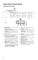
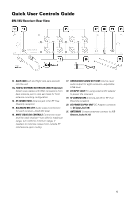
System Operation 8W-1KU Receiver Installing Antennas Install antennas on back by connecting the two Antennas (21) included with your system onto the two RF Connectors (14/19) located on the back of the 8W-1KU receivers. The two antennas must be installed in order for the diversity circuit to work properly. The optimal positions of the antennas are 45° from the receiver and 90° from each other. For maximum range, it is always best to maintain a line-of-sight (no obstructions) between the receiver antennas and the transmitter at all times whenever possible. Once the receiver is connected to the power source, press the Power Button (1) for two seconds. The LCD Displays (8) will light (showing Group, Channel, RF Level Meter, and Output Volume). The Diversity A/B (2) and the AF PEAK LED (3) are off at this time and will display when the transmitter is on and the audio is transmitted. To turn off, press the Power button for two seconds. The LCD will display "OFF" then the backlight will turn off indicating the receivers are off. Connect either the ¼" Unbalanced Audio Out (17) or each XLR Balanced Mic Outs (15) to your mixing board, effect, or amplifier inputs (See Connecting the Audio Outputs section). For front antenna installation, first install optional FAMK-2 Antenna Extension Cables (13a), insert one end of each BNC cables into a rack ear hole and secure using the removable nuts. Lock other end of the BNC cables to an RF Connector (14/19) on the back of the unit. Then connect the two antennas to the front of the receiver. Rack-mounting the Receiver The Nady 8W-1KU receiver wireless system has built-In Rack Ears (13). Simply attach the rackears with supplied screws on both sides and install the receiver onto the rack. Note: Do not mount the receiver on a rack directly above an amplifier or other source of high heat. This could degrade the performance of the 8W-1KU. Always ensure adequate airflow and heat dissipation in any rack configuration. Powering the Receiver To power the receivers, plug the provided AC/ DC Power Supply (20) adapter into the DC Input Jack (18) on the back of the receivers, then plug the adapter into an AC outlet. Note: Any regulated +12VDC source with minimum 2500mA capacity can also be used. Button Function on the Receiver The Power Button (1) is used to turn ON or OFF all receivers at the same time. When this power button is pressed for two seconds, the blue backlights on the LCD Displays (8) will light up indicating the receivers are on. Press the Power button again for two seconds to turn off the receivers. The backlight on the LCD will display "OFF" indicating the receivers are off. At power-off the 8W-1KU receivers will store the last settings entered and re-display them at power-on. It can be reprogrammed to any new Group/Channel, or Volume level. The default factory setting is Group 01 (Receiver 1) and 02 (Receiver 2), 03 (Receiver 3) and 04 (Receiver 4), Group 05 (Receiver 5) and 06 (Receiver 6), 07 (Receiver 7) and 08 (Receiver 8), Channel 00 and Volume 63 for all receivers. The (Up) or (Down) Buttons (7) are active while in the Set mode, or can be used to change Volume Level (11) at anytime. When the Set Button (6) is repeatedly pressed the LCD Display (8) menus will cycle in the following order: MAIN MENU > GROUP > CHANNEL > VOLUME > MAIN MENU (repeats) 8
-
 1
1 -
2
-
 3
3 -
 4
4 -
 5
5 -
 6
6 -
 7
7 -
 8
8 -
 9
9 -
 10
10 -
 11
11 -
 12
12 -
 13
13 -
14
-
15
-
16
-
17
-
18
-
19
-
20
-
21
-
22
-
23
-
24
 |
 |
