Nady 8W-1KU Manual - Page 4
Quick User Controls Guide
 |
View all Nady 8W-1KU manuals
Add to My Manuals
Save this manual to your list of manuals |
Page 4 highlights
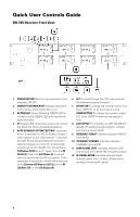
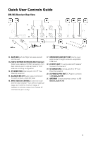
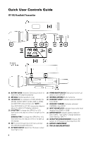
Quick User Controls Guide 8W-1KU Receiver: Front View 1. POWER BUTTON Press for two seconds to turn receivers ON-OFF 2. DIVERSITY A/B INDICATOR Indicates receiver A or B is active when transmitter is on 3. AF PEAK LED Shows flickering GREEN LED is normal or solid GREEN LED is for maximum audio allowable 4. IR Infrared LED transmitter window for linking the RX to the TX for download frequency 5. AUTO-SCAN/ASC (IR SYNC) BUTTON Long press (hold ~2 seconds) for AUTO-SCAN to locate a clear channel to use. Short press (~1 second) to make IR link and download the receiver's selected frequency to the TX. To download, positioning the HT-1KU/BT-1KU transmitters' IR Window (34/43) by 6-12" away from the RX IR LED (4). Press the ASC Button (5) once and wait one second for the RX to respond. If the download is successful, the RX will show one of the Diversity A/B Antenna LED (2) and full RF LCD Bars (12) on the LCD Display (8) 6. SET To scroll through the LCD menu and set the selected program/function 7. UP BUTTON To change the receiver output VOL level, GRP/CH, up by one step at a time DOWN BUTTON To change the receiver output VOL level, GRP/CH down by one step at a time 8. LCD DISPLAY For indication of GRP (00-09)/CH (00-99), RF signal strength indicator 1-6 bars, and Volume Levels (0-63) 9. FREQUENCY GROUP Indicates selected GROUP from 00-09 10. FREQUENCY CHANNEL Indicates selected CHANNEL from 00-99 11. SUM VOLUME LEVEL Indicates selected LINE output level from 00-63, (63 is loudest output) 12. RF SIGNAL METER Indicates received signal strength levels from 1-6 bars, (6 bars show excellent incoming RF signal) 4
-
 1
1 -
 2
2 -
 3
3 -
 4
4 -
 5
5 -
 6
6 -
 7
7 -
 8
8 -
 9
9 -
 10
10 -
11
-
12
-
13
-
14
-
15
-
16
-
17
-
18
-
19
-
20
-
21
-
22
-
23
-
24
 |
 |
