Nady 8W-1KU Manual - Page 6
HT-1KU Handheld Transmitter
 |
View all Nady 8W-1KU manuals
Add to My Manuals
Save this manual to your list of manuals |
Page 6 highlights
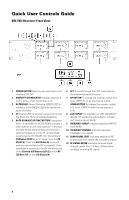
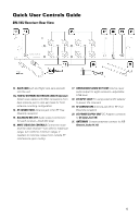
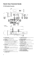
Quick User Controls Guide HT-1KU Handheld Transmitter 22. BATTERY COVER Unscrew CW and pull down to insert two AA alkaline batteries 23. MIC BALL Windscreen/dust cover 24. LCD DISPLAY For indication of GRP (00-09)/ CH (00-99), AUDIO INPUT LEVEL (0dB to -30dB), and BATTERY status (5 bars and "BATT.") See 30/31/32/33 in HT-1KU transmitter diagram above for detail LCD display indicators. 25. UP BUTTON To change the GRP/CH or VOL level up by one step at a time or to light up the display DOWN BUTTON To change the GRP/CH or VOL level down by one step at a time or to light up the display 26. SET To scroll through the LCD menu and set the selected program/function 27. RF POWER SWITCH Select the TX power output level high or low 28. POWER ON/OFF SWITCH Slide power switch up/ down to turn ON-OFF 29. INTERNAL ANTENNA Built-in antenna 30. FREQUENCY GROUP Indicates selected GROUP from 00-09 31. FREQUENCY CHANNEL Indicates selected CHANNEL from 00-99 32. INPUT VOLUME LEVEL Indicates input audio level ranging from 00dB to -30dB 33. BATTERY METER Indicates battery status (5 bars=100%, 1 bar=20%). Change batteries when flashing "BATT") 34. IR RECEPTOR SENSOR/WINDOW Infrared LED sensor for IR frequency download from RX 35. BATTERY COMPARTMENT 36. TWO AA ALKALINE BATTERIES 6
-
 1
1 -
 2
2 -
 3
3 -
 4
4 -
 5
5 -
 6
6 -
 7
7 -
 8
8 -
 9
9 -
 10
10 -
 11
11 -
 12
12 -
13
-
14
-
15
-
16
-
17
-
18
-
19
-
20
-
21
-
22
-
23
-
24
 |
 |
