Nady 8W-1KU Manual - Page 7
BT-1KU Bodypack Transmitter LT, LT/HM or GT
 |
View all Nady 8W-1KU manuals
Add to My Manuals
Save this manual to your list of manuals |
Page 7 highlights
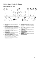
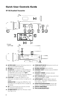
Quick User Controls Guide BT-1KU Bodypack Transmitter (LT, LT/HM or GT) 37. INPUT JACK 3.5mm locking mini jack for connecting audio input cord from lapel mic (LT), Headmic™ (LT/HM), or instrument (GT) 38. POWER OFF/MUTE/ON SWITCH Slide power switch to ON or OFF to turn ON-OFF, set to MUTE to turn power on with audio muted 39. ANTENNA Permanently attached antenna 40. LCD DISPLAY For indication of GRP (00-09)/CH (00-99), AUDIO INPUT LEVEL (0dB to -30dB), and BATTERY status (5 bars and "BATT.") See 30/31/32/33 in HT-1KU transmitter diagram above for detail LCD display indicators. 41. UP BUTTON To change the GRP/CH or VOL level up by one step at a time or to light up the display DOWN BUTTON To change the GRP/CH or VOL level down by one step at a time or to light up the display 42. SET BUTTON To scroll LCD menu and set the selected program/function 43. IR RECEPTOR SENSOR Infrared LED sensor for linking the TX to the RX during IR frequency download 44. RF POWER HI/LOW SWITCH Select the TX power output level high or low 45. BATTERY COMPARTMENT 46. LATCHING BATTERY COMPARTMENT DOOR 47. TWO AA ALKALINE BATTERIES 48. BELT CLIP (on back of unit)-removable clip can be set for top of transmitter pointing either up or down 7
-
 1
1 -
 2
2 -
 3
3 -
 4
4 -
 5
5 -
 6
6 -
 7
7 -
 8
8 -
 9
9 -
 10
10 -
 11
11 -
 12
12 -
13
-
14
-
15
-
16
-
17
-
18
-
19
-
20
-
21
-
22
-
23
-
24
 |
 |
