Magic Chef MCSRG24S User Manual 1 - Page 6
Location Requirements
 |
View all Magic Chef MCSRG24S manuals
Add to My Manuals
Save this manual to your list of manuals |
Page 6 highlights
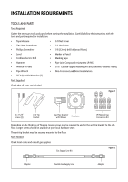
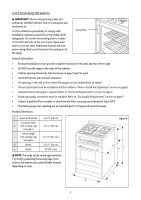
Location Requirements important: Observe all governing codes and ordinances. Do not obstruct flow of combustion and ventilation air. It is the installer's responsibility to comply with installation clearances specified on the model/serial rating plate. The model/serial rating plate is located on the left hand side of the oven frame. Open oven door to view the label. Additional element and oven power rating labels can be found on the back panel of the range. Rating Plate Figure 3 General Information • Recessed installations must provide complete enclosure of the sides and rear of the range. • Do not seal the range to the sides of the cabinets. • Cabinet opening dimensions that are shown on page 7 must be used. • Given dimensions are minimum clearances. • All openings in the wall or floor where the range is to be installed must be sealed. • The anti-tip bracket must be installed to the floor. Refer to "How to Install Anti-Tip Bracket" section on page 12. • Grounded electrical supply is required. Refer to "Electrical Requirements" section on page 9. • Proper gas supply connection must be available. Refer to "Gas Supply Requirements" section on page 9. • Contact a qualified floor installer to check that the floor covering can withstand at least 200°F. • If installing range over carpeting use an insulated pad or 1/4 plywood under the range. Product Dimensions a Depth with Handle Cooktop Height b with Leveling Legs Screwed in Overall Height c with Leveling Legs Screwed in d Width e Depth 26-3/4" (68 cm) 35-1/2" (90 cm) 37-3/5" (95.5 cm) 23-2/5" (60 cm) 25" (63.5 cm) note: The range can be raised approximately 1" (2.5cm) by adjusting the leveling legs. Front of door and drawer may extend farther forward depending on style. Figure 4 a bc e d 6
-
 1
1 -
 2
2 -
 3
3 -
 4
4 -
 5
5 -
 6
6 -
 7
7 -
 8
8 -
 9
9 -
 10
10 -
 11
11 -
 12
12 -
13
-
14
-
15
-
16
-
17
-
18
-
19
-
20
-
21
-
22
-
23
-
24
-
25
-
26
-
27
-
28
-
29
-
30
-
31
-
32
-
33
-
34
-
35
-
36
-
37
-
38
-
39
-
40
 |
 |
