LiftMaster SL585101U SL585151U Installation Manual - Page 48
ACCESSORIES, AUX Relay
 |
View all LiftMaster SL585101U manuals
Add to My Manuals
Save this manual to your list of manuals |
Page 48 highlights
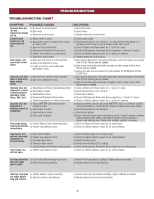
TROUBLESHOOTING TROUBLESHOOTING CHART continued... SYMPTOM POSSIBLE CAUSES Shadow loop does not keep gate at open limit. a) Vehicle detector setup incorrectly b) Defective vehicle loop detector Obstruction in a) Force adjustment needed gate's path does not cause gate to stop and reverse Photoelectric sensor does not stop or reverse gate. a) Incorrect photoelectric sensor wiring b) Defective photoelectric sensor c) Photoelectric sensors installed too far apart Edge Sensor does a) Incorrect edge sensor wiring not stop or reverse b) Defective edge sensor gate. Alarm sounds for 5 minutes or alarm sounds with a command. On dual-gate system, incorrect gate opens first or closes first. Alarm beeps when running. a) Double entrapment occurred (two obstructions within a single activation) a) Incorrect Bipart switch setting a) Expansion board setting b) Constant pressure to open or close is given SOLUTIONS a) Review Shadow loop detector settings. Adjust settings as needed. b) Replace defective Shadow loop detector. a) Refer to the Adjustment section to conduct the obstruction test and perform the proper force adjustment that is needed. a) Check photoelectric sensor wiring. Retest that obstructing photoelectric sensor causes moving gate to stop, and may reverse direction. b) Replace defective photoelectric sensor. Retest that obstructing photoelectric sensor causes moving gate to stop, and may reverse direction. c) Move the photoelectric sensors closer together or use edge sensors instead. a) Check edge sensor wiring. Retest that activating edge sensor causes moving gate to stop and reverse direction. b) Replace defective edge sensor. Retest that activating edge sensor causes moving gate to stop and reverse direction. a) Check for cause of entrapment (obstruction) detection and correct. Press the reset button to shut off alarm and reset the operator. a) Change setting of both operator's Bipart switch settings. One operator should have Bipart switch ON (operator that opens second) and the other operator should have Bipart switch OFF (operator that opens first) a) Pre-warning is set to "ON" b) Constant pressure to open or closed is given Expansion board function not controlling gate. Maglock not working correctly. Solenoid lock not working correctly. Quick Close not working correctly. a) Defective main board to expansion board wiring b) Incorrect input wiring to expansion board c) Defective expansion board or defective main board a) Maglock wired incorrectly a) Solenoid wired incorrectly a) Quick Close setting incorrect b) Interrupt loop detector c) Defective Expansion board a) Check main board to expansion board wiring. If required, replace wire cable. b) Check wiring to all inputs on expansion board. c) Replace defective expansion board or defective main board a) Check that Maglock is wired to N.C. and COM terminals. Check that Maglock has power (do not power maglock from control board accessory power terminals). If shorting lock's NO and COM wires does not activate Maglock, then replace Maglock or Maglock wiring (refer to Wiring Diagrams). a) Check that Solenoid is wired to N.O. and COM terminals. Check that Solenoid has power (do not power solenoid from control board accessory power terminals). If shorting lock's NC and COM wires does not activate Solenoid, then replace Solenoid lock or Solenoid wiring (refer to Wiring Diagrams). a) Check that Quick Close setting is ON b) Check operation of Interrupt Loop detector c) Replace defective Expansion board Anti-Tailgating not working correctly. a) Anti-Tail setting incorrect b) Interrupt loop detector c) Defective Expansion board a) Check that Anti-Tail setting is ON b) Check operation of Interrupt Loop detector c) Replace defective Expansion board AUX Relay not working correctly. a) AUX Relay setting incorrect b) AUX Relay wiring incorrect c) Defective Expansion board a) Check AUX Relay switches settings b) Check that wiring is connected to either N.O. and COM or to N.C. and COM. c) Set AUX Relay to another setting and test. Replace defective expansion board. 46
-
 1
1 -
2
-
3
-
4
-
5
-
6
-
7
-
8
-
9
-
10
-
11
-
12
-
13
-
14
-
15
-
16
-
17
-
18
-
19
-
20
-
21
-
22
-
23
-
24
-
25
-
26
-
27
-
28
-
29
-
30
-
31
-
32
-
33
-
34
-
35
-
36
-
37
-
38
-
39
-
40
-
41
-
42
-
 43
43 -
 44
44 -
 45
45 -
 46
46 -
 47
47 -
 48
48 -
 49
49 -
 50
50 -
 51
51 -
 52
52
 |
 |
