LiftMaster SL585101U SL585151U Installation Manual - Page 20
STEP 5 continued, SINGLE PHASE
 |
View all LiftMaster SL585101U manuals
Add to My Manuals
Save this manual to your list of manuals |
Page 20 highlights
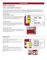
INSTALLATION STEP 5 (continued) POWER WIRING SINGLE PHASE The operator is field configurable for usage at 120, 208, and 240 Vac. Factory default is 120 Vac. For 208 Vac Operation Unplug the motor harness from the "120V" receptacle on the power board and plug the harness in to the "208V / 240V" receptacle. Swap the orange and red transformer wires (the red wire connects to the 240V position and the orange wire connects to the 208V position). For 480 Vac Operation Unplug the motor harness from the "120V" receptacle on the power board and plug the harness into the "208V / 240V" receptacle. 1. Make sure the AC power switch on the operator is OFF (the AC power switch will turn the incoming power ON or OFF). 2. Turn off the AC power from the main power source circuit breaker. 3. Run the AC power wires to the junction box on the operator. 4. Remove the junction box cover. 5. Connect the operator wires to line power via the white, black, and green wires in the junction box. Follow the table in the specification section for the appropriate wire gauge for your application. 6. Replace the junction box cover. Ensure the wires are not pinched. 7. Turn on the AC power from the main power source circuit breaker. 8. Turn on the AC power switch. NOTES: The 120 Vac accessory power outlets are not switched and will be live when 120 Vac incoming power is supplied to the operator regardless of whether the AC power switch is on or off. The 120 Vac accessory power outlets are automatically disabled when the operator is configured for 208V or 240V operation. SINGLE PHASE POWER BOARD J10 J8 J15 J14 J13 CURRENT SENSOR SWITCH (YELLOW) PWR IN HOT (BLACK) 120V (BLACK) OUTLET (WHITE) 120V J11 J12 J2 J4 J6 J16 SWITCH (ORANGE) COMM (WHITE) 120V (BLACK) 208V (RED) 240V (ORANGE) TRANSFORMER 240V J9 J17 J5 J3 J7 Red and orange transformer wires Receptacles SINGLE PHASE OPERATOR 120V PWR IN NEUTRAL (WHITE) J1 240V Motor Harness Black Green AC Power Switch JUNCTION BOX White INCOMING POWER 18
-
 1
1 -
2
-
3
-
4
-
5
-
6
-
7
-
8
-
9
-
10
-
11
-
12
-
13
-
14
-
 15
15 -
 16
16 -
 17
17 -
 18
18 -
 19
19 -
 20
20 -
 21
21 -
 22
22 -
 23
23 -
 24
24 -
 25
25 -
26
-
27
-
28
-
29
-
30
-
31
-
32
-
33
-
34
-
35
-
36
-
37
-
38
-
39
-
40
-
41
-
42
-
43
-
44
-
45
-
46
-
47
-
48
-
49
-
50
-
51
-
52
 |
 |
