Invacare SPREEGT Owners Manual - Page 87
Contracture Assembly Angle Adjustment, Using the Optional Quick-Release Pin
 |
View all Invacare SPREEGT manuals
Add to My Manuals
Save this manual to your list of manuals |
Page 87 highlights
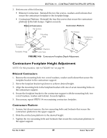
SECTION 14-CONTRACTURE FOOTPLATE OPTION Contracture Assembly Angle Adjustment NOTE: For this procedure, refer to FIGURE 14.3. 1. Perform one of the following: • Bilateral Contracture - Remove the mounting bolt and locknut used to lock the angle adjustment of the contracture assembly. • Contracture Platform - Remove the two mounting bolts and locknuts that lock the angle adjustment of the contracture assembly. 2. Lift the contracture support up/down to achieve the desired angle. 3. Perform one of the following: • Bilateral Contracture - Align the mounting hole in the contracture support with one of seven mounting holes on the angle adjustment bracket. • Contracture Platform - Align the upper support mounting hole with one of four mounting holes in the angle adjustment plate. 4. Reinstall the mounting bolts (s) and locknut(s) to lock the angle adjustment of the contracture assembly. Securely tighten. Locknut Bilateral Contracture Mounting Bolt Angle Adjustment Bracket Contracture Platform Angle Locknuts Adjustment Plate Mounting Hole # Bolts 4 3 2 1 Angle Upper Support Contracture Support Mounting Holes FIGURE 14.3 Contracture Assembly Angle Adjustment Using the Optional Quick-Release Pin ƽ WARNING If not installed at time of shipment, the quick-release pin MUST be installed by a qualified technician only, using a 1/8-inch pop rivet. NOTE: For this procedure, refer to FIGURE 14.4 on page 88. NOTE: This procedure applies to the bilateral contracture footplate only. NOTE: The quick-release pin replaces the mounting screw that is used to lock the angle adjustment of the contracture support. Part No 1125027 87 Solara®/Spree GT™
-
 1
1 -
2
-
3
-
4
-
5
-
6
-
7
-
8
-
9
-
10
-
11
-
12
-
13
-
14
-
15
-
16
-
17
-
18
-
19
-
20
-
21
-
22
-
23
-
24
-
25
-
26
-
27
-
28
-
29
-
30
-
31
-
32
-
33
-
34
-
35
-
36
-
37
-
38
-
39
-
40
-
41
-
42
-
43
-
44
-
45
-
46
-
47
-
48
-
49
-
50
-
51
-
52
-
53
-
54
-
55
-
56
-
57
-
58
-
59
-
60
-
61
-
62
-
63
-
64
-
65
-
66
-
67
-
68
-
69
-
70
-
71
-
72
-
73
-
74
-
75
-
76
-
77
-
78
-
79
-
80
-
81
-
 82
82 -
 83
83 -
 84
84 -
 85
85 -
 86
86 -
 87
87 -
 88
88 -
 89
89 -
 90
90 -
 91
91 -
 92
92 -
93
-
94
-
95
-
96
-
97
-
98
-
99
-
100
 |
 |
