Invacare SPREEGT Owners Manual - Page 83
Adjusting the Gas Cylinders
 |
View all Invacare SPREEGT manuals
Add to My Manuals
Save this manual to your list of manuals |
Page 83 highlights
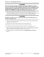
Squeeze Trigger Release Lever To Align Mounting Holes (STEP 7, 8) SECTION 13-RECLINER BACK OPTION Actuator Housing Jam Nut (STEPS 1, 4, 6) Cylinder Rod Gas Cylinder Button Head Cap Screw (STEPS 2, 9) Bracket Spacer (STEPS 2, 9) Washer (STEPS 2, 9) Locknut (STEPS 2,9) Nylon Washer (STEPS 2, 9) FIGURE 13.4 Replacing the Gas Cylinders Adjusting the Gas Cylinders ƽ WARNING Both gas cylinders MUST be operational and adjusted properly BEFORE using the recliner. DO NOT operate the recliner if only one of the gas cylinders is operational or adjusted properly. NOTE: For this procedure, refer to FIGURE 13.5 on page 85. Determining Necessary Adjustments NOTE: The gas cylinders are controlled by the trigger release levers mounted on the opposite sides of the gas cylinders. The right trigger release lever controls the left gas cylinder, and the left trigger release lever controls the right gas cylinder. Refer to the following chart to determine the necessary adjustments: Part No 1125027 83 Solara®/Spree GT™
-
 1
1 -
2
-
3
-
4
-
5
-
6
-
7
-
8
-
9
-
10
-
11
-
12
-
13
-
14
-
15
-
16
-
17
-
18
-
19
-
20
-
21
-
22
-
23
-
24
-
25
-
26
-
27
-
28
-
29
-
30
-
31
-
32
-
33
-
34
-
35
-
36
-
37
-
38
-
39
-
40
-
41
-
42
-
43
-
44
-
45
-
46
-
47
-
48
-
49
-
50
-
51
-
52
-
53
-
54
-
55
-
56
-
57
-
58
-
59
-
60
-
61
-
62
-
63
-
64
-
65
-
66
-
67
-
68
-
69
-
70
-
71
-
72
-
73
-
74
-
75
-
76
-
77
-
 78
78 -
 79
79 -
 80
80 -
 81
81 -
 82
82 -
 83
83 -
 84
84 -
 85
85 -
 86
86 -
 87
87 -
 88
88 -
89
-
90
-
91
-
92
-
93
-
94
-
95
-
96
-
97
-
98
-
99
-
100
 |
 |
