Invacare ORBITB Owners Manual - Page 65
Anti-tippers/wheel, Locks
 |
View all Invacare ORBITB manuals
Add to My Manuals
Save this manual to your list of manuals |
Page 65 highlights
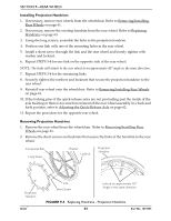
SECTION 10-ANTI-TIPPERS/WHEEL LOCKS SECTION 10-ANTI-TIPPERS/WHEEL LOCKS ƽ WARNING After any adjustments, repair or service and before use, make sure all attaching hardware is tightened securely. Otherwise injury or damage may occur. Foot Activated Wheel Lock Procedures NOTE: For this procedure, refer to FIGURE 10.1 on page 66. Installing/Removing Foot Activated Wheel Locks NOTE: Foot activated wheel locks can only be used with 12‐inch rear wheels. 1. Remove the rear wheels. Refer to Removing/Installing Rear Wheels on page 61. 2. Remove existing wheel locks. Refer to Installing/Removing Hand Activated Wheel Locks on page 66. 3. Remove the two set screws that secure the two halves of the wheel lock clamp together. 4. Position clamp onto lower tube of wheelchair frame near vertical tube of the wheelchair frame. Reinstall set screws. Loosely tighten. 5. Repeat STEPS 1‐2 for opposite clamp. 6. Align the slider bars, of the foot activated wheel lock assembly, with the clamps on the lower tube of wheelchair. 7. Push slider bars completely forward into clamps. NOTE: The clamps of the wheel lock may need to be repositioned forward to accommodate reinstallation of the rear wheels. 8. Reinstall the rear wheels. Refer to Removing/Installing Rear Wheels on page 61. 9. Adjust the position of the wheel lock. Refer to Adjusting the Wheel Lock on page 67. Using Foot Activated Wheel Locks 1. To engage, push down on crossbar of wheel lock assembly. 2. To disengage, lift up on crossbar or release lever. Part No. 1073955 65 Orbit™
-
 1
1 -
2
-
3
-
4
-
5
-
6
-
7
-
8
-
9
-
10
-
11
-
12
-
13
-
14
-
15
-
16
-
17
-
18
-
19
-
20
-
21
-
22
-
23
-
24
-
25
-
26
-
27
-
28
-
29
-
30
-
31
-
32
-
33
-
34
-
35
-
36
-
37
-
38
-
39
-
40
-
41
-
42
-
43
-
44
-
45
-
46
-
47
-
48
-
49
-
50
-
51
-
52
-
53
-
54
-
55
-
56
-
57
-
58
-
59
-
 60
60 -
 61
61 -
 62
62 -
 63
63 -
 64
64 -
 65
65 -
 66
66 -
 67
67 -
 68
68 -
 69
69 -
 70
70 -
71
-
72
-
73
-
74
-
75
-
76
-
77
-
78
-
79
-
80
-
81
-
82
-
83
-
84
 |
 |