Intel SR1300 Product Specification - Page 56
Floppy/CDROM and Floppy/DVDROM Module, Interface Assemblies
 |
View all Intel SR1300 manuals
Add to My Manuals
Save this manual to your list of manuals |
Page 56 highlights
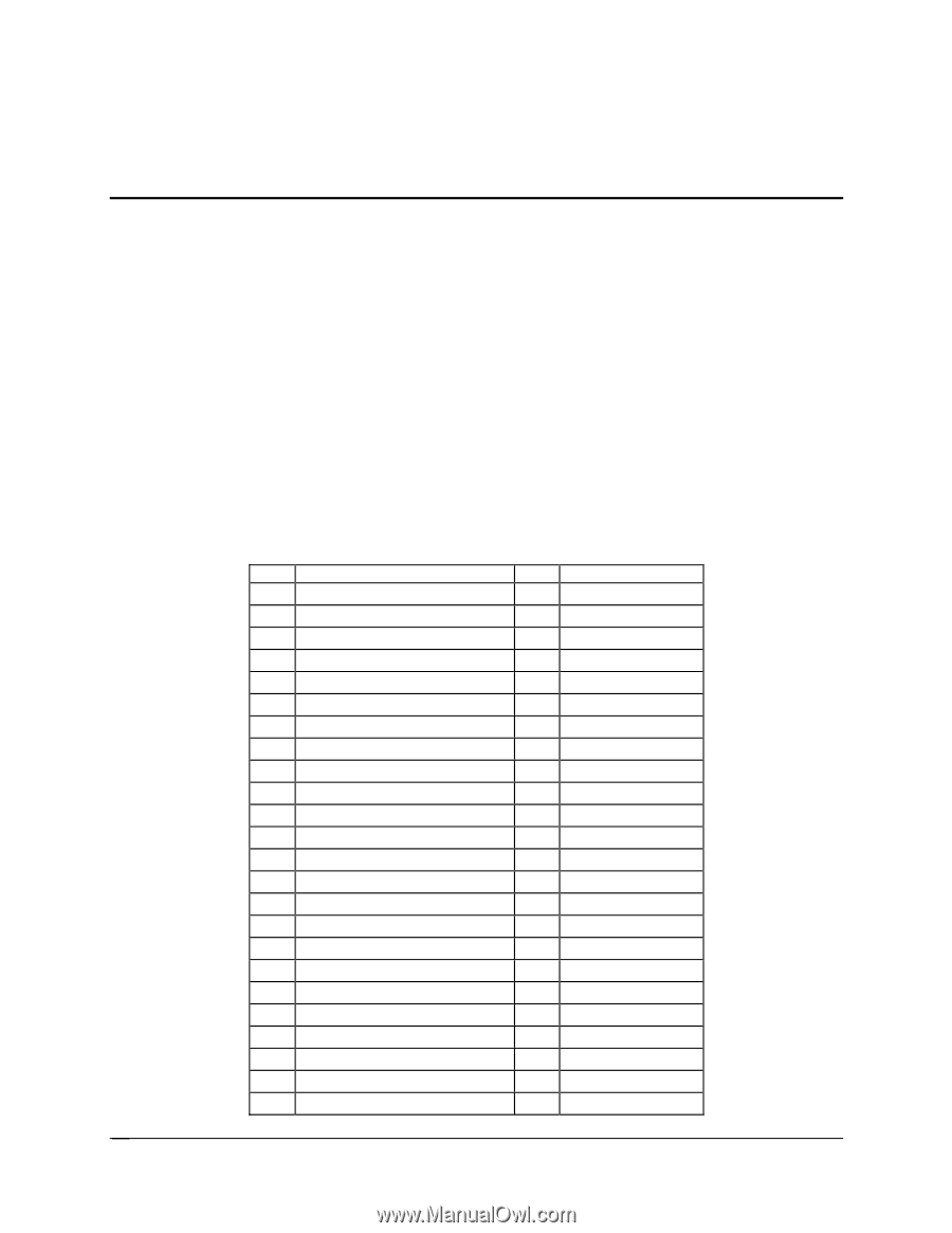
Floppy/CDROM and Floppy/DVDROM Module Interface Assemblies 1U Server Chassis SR1300 8. Floppy/CDROM and Floppy/DVDROM Module Interface Assemblies Two modules are available for use in the server chassis SR1300. Both support a floppy disk drive, while one contains a CDROM drive and the other a DVDROM drive. The interface assembly will be referred to as FDD/CDROM (though it supports DVDROM drives also). The FDD/CDROM interface assembly consists of two pieces: a 60-pin high-density connector located on both the SCSI and ATA backplanes, and a raised FDD/CD daughter board. In the SCSI configuration, this assembly allows the daughter board to sit directly over the third SCA2 SCSI connector, allowing for either a third SCSI hard drive or a floppy/CDROM or floppy/DVD module to be used in the flex bay. Both the SCSI and ATA backplanes provide a pathway for FDD/CD signals from the 100-pin floppy/FP/IDE connector to the high-density 60-pin (Molex: 52760-0608) daughter board connector. The following table provides the connector pinout. Table 29. 60-Pin Daughter Card Connector Pinout Pin 1 CDR_D1 Name 3 CDR_D13 5 CDR_D2 7 CDR_D12 9 CDR_D3 11 CDR_D11 13 CDR_D4 15 CDR_D10 17 CDR_D5 19 CDR_D9 21 CDR_D6 23 CDR_D8 25 CDR_D7 27 CHP3_CDRST_L 29 GND 31 GND 33 GND *35 PWRCNTR1_FOR_IDE_HSBP *37 PWRCNTR2_FOR_IDE_HSBP 39 ACTIVE_L 41 FDD_INDEX_L 43 FDD_DSKCHG_L 45 FDD_DIR_L 47 FDD_WDATA_L Pin Name 2 CDR_D0 4 CDR_D14 6 CDR_D15 8 CDR_IOW_L 10 CDR_IOR_L 12 CDR_IRDY 14 CDR_IRQ 16 CDR_ADDR1 18 CDR_DACK_L 20 CDR_ADDR0 22 CDR_ADDR2 24 CDR_CS1_L 26 CDR_CS3_L 28 CDR_DREQ 30 GND 32 GND 34 GND 36 GND 38 CD_FDD_PRSN_L 40 FDD_HDSEL_L 42 FDD_WPROT_L 44 FDD_WGATE_L 46 FDD_STEP_L 48 FDD_MTR0_L 46 Revision 1.2 Intel order number A94544-004
-
 1
1 -
2
-
3
-
4
-
5
-
6
-
7
-
8
-
9
-
10
-
11
-
12
-
13
-
14
-
15
-
16
-
17
-
18
-
19
-
20
-
21
-
22
-
23
-
24
-
25
-
26
-
27
-
28
-
29
-
30
-
31
-
32
-
33
-
34
-
35
-
36
-
37
-
38
-
39
-
40
-
41
-
42
-
43
-
44
-
45
-
46
-
47
-
48
-
49
-
50
-
 51
51 -
 52
52 -
 53
53 -
 54
54 -
 55
55 -
 56
56 -
 57
57 -
 58
58 -
 59
59 -
 60
60 -
 61
61 -
62
-
63
-
64
-
65
-
66
-
67
-
68
-
69
-
70
-
71
-
72
-
73
-
74
-
75
-
76
-
77
-
78
-
79
 |
 |