Intel SR1300 Product Specification - Page 50
ATA Backplane Functional Architecture
 |
View all Intel SR1300 manuals
Add to My Manuals
Save this manual to your list of manuals |
Page 50 highlights
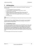
ATA Backplane 1U Server Chassis SR1300 Figure 22. ATA Backplane Layout 7.2 ATA Backplane Functional Architecture The ATA backplane is made up of the following functional blocks: • ATA100 bus with IDE connectors, which are combined with 4-pin power connectors • ATA drive power control • Peripheral/front panel interfaces The figure below shows the functional blocks of the ATA backplane. 40 Revision 1.2 Intel order number A94544-004
-
 1
1 -
2
-
3
-
4
-
5
-
6
-
7
-
8
-
9
-
10
-
11
-
12
-
13
-
14
-
15
-
16
-
17
-
18
-
19
-
20
-
21
-
22
-
23
-
24
-
25
-
26
-
27
-
28
-
29
-
30
-
31
-
32
-
33
-
34
-
35
-
36
-
37
-
38
-
39
-
40
-
41
-
42
-
43
-
44
-
 45
45 -
 46
46 -
 47
47 -
 48
48 -
 49
49 -
 50
50 -
 51
51 -
 52
52 -
 53
53 -
 54
54 -
 55
55 -
56
-
57
-
58
-
59
-
60
-
61
-
62
-
63
-
64
-
65
-
66
-
67
-
68
-
69
-
70
-
71
-
72
-
73
-
74
-
75
-
76
-
77
-
78
-
79
 |
 |

ATA Backplane
1U Server Chassis SR1300
Revision 1.2
Intel order number A94544-004
40
Figure 22. ATA Backplane Layout
7.2
ATA Backplane Functional Architecture
The ATA backplane is made up of the following functional blocks:
•
ATA100 bus with IDE connectors, which are combined with 4-pin power connectors
•
ATA drive power control
•
Peripheral/front panel interfaces
The figure below shows the functional blocks of the ATA backplane.