Intel SR1300 Product Specification - Page 38
SCSI Backplane Configuration Jumpers, SCSI Backplane Functional Architecture
 |
View all Intel SR1300 manuals
Add to My Manuals
Save this manual to your list of manuals |
Page 38 highlights
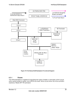
Hot-Swap SCSI Backplane 1U Server Chassis SR1300 6.2 SCSI Backplane Configuration Jumpers The following table describes the settings and functionality of the jumper block used on the SR1300 hot-swap SCSI backplane. Table 19. Hot-Swap Backplane Configuration Jumpers Option Firmware Update Flash Boot Block Write Location J4 J4 Description Placing this jumper in the "FORCE UPDATE" position forces external firmware update of the program code stored in Flash memory. Placing this jumper in the "NORMAL OPERATION" position allows normal operation This jumper allows the boot block of the program flash to be updated. "NORMAL OPERTATION" (default) does not allow the boot block to be written to. "WRITE" allows updating of the boot block 6.3 SCSI Backplane Functional Architecture Functionality of the SCSI backplane begins at power-up. The microprocessor boots up via code residing in the flash boot block. The SCSI backplane is capable of downloading firmware via the IMB in-order to update the flash executable code. The following figure shows the functional blocks of the hot-swap SCSI backplane. 28 Revision 1.2 Intel order number A94544-004
-
 1
1 -
2
-
3
-
4
-
5
-
6
-
7
-
8
-
9
-
10
-
11
-
12
-
13
-
14
-
15
-
16
-
17
-
18
-
19
-
20
-
21
-
22
-
23
-
24
-
25
-
26
-
27
-
28
-
29
-
30
-
31
-
32
-
 33
33 -
 34
34 -
 35
35 -
 36
36 -
 37
37 -
 38
38 -
 39
39 -
 40
40 -
 41
41 -
 42
42 -
 43
43 -
44
-
45
-
46
-
47
-
48
-
49
-
50
-
51
-
52
-
53
-
54
-
55
-
56
-
57
-
58
-
59
-
60
-
61
-
62
-
63
-
64
-
65
-
66
-
67
-
68
-
69
-
70
-
71
-
72
-
73
-
74
-
75
-
76
-
77
-
78
-
79
 |
 |
