Intel 510T User Guide - Page 19
Installing a Module - user guide
 |
UPC - 735858114219
View all Intel 510T manuals
Add to My Manuals
Save this manual to your list of manuals |
Page 19 highlights
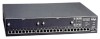
C H A P T E R 1 Intel Express 510T Switch Introduction Static-free working area Avoiding damage to the circuit board Installing a module Installing a Module You can increase the connectivity options of your switch by installing a module. Warning Modules are not designed to be installed in, or removed from, the switch while it is in operation. You must power off the switch before attempting to install or remove a module. The module's printed circuit board is an Electrostatic Sensitive Device and should be handled only in a static-free working area; otherwise, the printed circuit board may fail or be degraded. If you remove the plate covering the slot on the front of the switch, for example, to install or remove a module, follow this procedure to avoid damage to your printed circuit board: Warning Do not remove the plate unless the switch is disconnected from the main power supply. 1 Disconnect the switch from the main power supply. 2 Ground the switch before you handle the printed circuit board. 3 Connect yourself to a non-painted/non-isolated part of the grounded switch (for example the back panel) using a wrist strap with 1MΩ resistance to ensure that you carry the same electrostatic charge as the enclosure. 4 Remove the plate covering the slot. To install a module: 1 If the switch is already operational, disconnect it from the main power supply. 2 Follow the instructions in "Avoiding damage to the circuit board" above. 3 Unscrew the screws of the plate covering the slot on the front of the switch. Save these screws and plate. 4 Insert the module into the slot (following the instructions in the module's User Guide). Place your thumbs just beneath the screws on the front panel of the module and push in the module. Secure it using the retaining screws. 9
-
 1
1 -
2
-
3
-
4
-
5
-
6
-
7
-
8
-
9
-
10
-
11
-
12
-
13
-
 14
14 -
 15
15 -
 16
16 -
 17
17 -
 18
18 -
 19
19 -
 20
20 -
 21
21 -
 22
22 -
 23
23 -
 24
24 -
25
-
26
-
27
-
28
-
29
-
30
-
31
-
32
-
33
-
34
-
35
-
36
-
37
-
38
-
39
-
40
-
41
-
42
-
43
-
44
-
45
-
46
-
47
-
48
-
49
-
50
-
51
-
52
-
53
-
54
-
55
-
56
-
57
-
58
-
59
-
60
-
61
-
62
-
63
-
64
-
65
-
66
-
67
-
68
-
69
-
70
-
71
-
72
-
73
-
74
-
75
-
76
-
77
-
78
-
79
-
80
-
81
-
82
-
83
-
84
-
85
-
86
-
87
-
88
-
89
-
90
-
91
-
92
-
93
-
94
-
95
-
96
-
97
-
98
-
99
-
100
-
101
-
102
-
103
-
104
-
105
-
106
-
107
-
108
-
109
-
110
-
111
-
112
-
113
-
114
-
115
-
116
-
117
-
118
-
119
-
120
-
121
-
122
-
123
-
124
-
125
-
126
-
127
-
128
-
129
-
130
-
131
-
132
-
133
-
134
-
135
-
136
-
137
-
138
-
139
-
140
-
141
-
142
-
143
-
144
 |
 |
