Intel 510T User Guide - Page 14
Reset or enter Maintenance Mode or Recov - express
 |
UPC - 735858114219
View all Intel 510T manuals
Add to My Manuals
Save this manual to your list of manuals |
Page 14 highlights
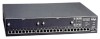
C H A P T E R 1 Intel Express 510T Switch Front panel ports These ports are on the front panel: Port CONSOLE port (DB-9) 24 x 10/100BaseTX ports (RJ-45) Function Connects a PC (running a VT100 emulation), a VT100 terminal or a modem to access the built-in Local Management program. Connects devices using Unshielded Twisted Pair (UTP) cabling complying to EIA 568A Category 5 or ISO/IEC 11801 Category 5 level D. Slots for modules After removing one or both of the cover plates, the modules can be inserted to expand the functionality of the switch. Front panel LED functions The LEDs on the front panel have the following functions: LED Port LEDs Green and Orange Status Power Temperature RPS (redundant power supply) Shows the status for... The operation of each port. The operation of the switch. The internal power supply. The internal temperature. The external, redundant power supply. Buttons The buttons on the front panel have the following functions: Button name Port Status Reset Function Shows the operational status of each port. Reset or enter Maintenance Mode or Recovery Mode 4
-
 1
1 -
2
-
3
-
4
-
5
-
6
-
7
-
8
-
 9
9 -
 10
10 -
 11
11 -
 12
12 -
 13
13 -
 14
14 -
 15
15 -
 16
16 -
 17
17 -
 18
18 -
 19
19 -
20
-
21
-
22
-
23
-
24
-
25
-
26
-
27
-
28
-
29
-
30
-
31
-
32
-
33
-
34
-
35
-
36
-
37
-
38
-
39
-
40
-
41
-
42
-
43
-
44
-
45
-
46
-
47
-
48
-
49
-
50
-
51
-
52
-
53
-
54
-
55
-
56
-
57
-
58
-
59
-
60
-
61
-
62
-
63
-
64
-
65
-
66
-
67
-
68
-
69
-
70
-
71
-
72
-
73
-
74
-
75
-
76
-
77
-
78
-
79
-
80
-
81
-
82
-
83
-
84
-
85
-
86
-
87
-
88
-
89
-
90
-
91
-
92
-
93
-
94
-
95
-
96
-
97
-
98
-
99
-
100
-
101
-
102
-
103
-
104
-
105
-
106
-
107
-
108
-
109
-
110
-
111
-
112
-
113
-
114
-
115
-
116
-
117
-
118
-
119
-
120
-
121
-
122
-
123
-
124
-
125
-
126
-
127
-
128
-
129
-
130
-
131
-
132
-
133
-
134
-
135
-
136
-
137
-
138
-
139
-
140
-
141
-
142
-
143
-
144
 |
 |
