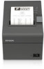
Epson TM-T20II Users Manual Hardware - Page 7
Connecting the Cables, WARNING, CAUTION - driver
 |
View all Epson TM-T20II manuals
Add to My Manuals
Save this manual to your list of manuals |
Page 7 highlights
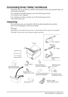
Connecting the Cables WARNING: Be sure to use the specified AC adapter [AC Adapter, C1 (Model: M235B)] only. CAUTION: For a serial interface, use a null modem cable. For a USB interface, do not turn on the printer before installing the printer driver. For using an Ethernet (10Base-T/100Base-TX) interface, do not connect a telephone line or a drawer kick-out cable to the Ethernet connector. Do not connect to electrical outlets close to devices that generate voltage fluctuations or electrical noise. In particular, stay clear of devices that use large electric motors. Never attempt to stretch the cables to enable a connection. The power cable must have adequate slack at all times during use. 1. Make sure the printer is turned off. 2. Connect the interface cable to the printer. For the shape of each connector, see the illustration below. (Mounted interfaces vary by the printer model.) RS-232 10BASE-T/ 100BASE-TX USB (Type B) 㻌 DC24V USB (Type A)* * for wireless LAN unit DK (Drawer kick-out connector) Note: When connecting the USB cable, fix the USB cable with the hook shown in the illustration below to prevent the cable from coming off. Hook TM-T20II User's Manual 7
-
 1
1 -
 2
2 -
 3
3 -
 4
4 -
 5
5 -
 6
6 -
 7
7 -
 8
8 -
 9
9 -
 10
10 -
 11
11 -
 12
12 -
13
-
14
-
15
-
16
-
17
-
18
-
19
-
20
-
21
 |
 |
