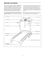
Epic Fitness Genesis 700 Uk Manual - Page 7
Start all four Console Bolts
 |
View all Epic Fitness Genesis 700 manuals
Add to My Manuals
Save this manual to your list of manuals |
Page 7 highlights
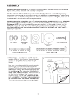
2. With the help of a second person, set the console assem- 2 bly on the Uprights (85). Make sure that no wires are pinched. Attach the console assembly with four Console Bolts (72), four Washers (96), and four Star Washers (67) (only one side is shown). Start all four Console Bolts 85 before tightening any of them. 67 96 72 Console Assembly 67 96 3. With the help of a second person, carefully tip the treadmill onto its side as shown. 3 Insert an Extension Leg (97) into the indicated bracket on the base of the Uprights (85). Make sure that the Extension Leg is turned so the Base Pad (81) is on the side shown. If necessary, use a rubber mallet to align the holes in the Extension Leg with the holes in the bracket. Attach the Extension Leg (97) with two Extension Leg Bolts (87), two Washers (96), and two Nuts (106) as shown. Firmly tighten the Nuts. With the help of a second person, carefully tip the treadmill onto its other side. Attach the other Extension Leg (not shown) as described above. Bracket 87 106 96 97 81 85 4. Attach the four Base Pads (81) to the base of the Uprights (85) in the indicated locations with four 1" Tek Screws 4 (82) and four Plastic Spacers (101). Note: One replace- ment Base Pad may be included. Use the Base Pad to re- place any Base Pad that becomes worn. With the help of a second person, carefully tip the treadmill down so the four Base Pads (81) are resting on the 101 floor and the Uprights (85) are in the vertical position. 101 81 82 85 101 55 81 82 101 7
-
 1
1 -
 2
2 -
 3
3 -
 4
4 -
 5
5 -
 6
6 -
 7
7 -
 8
8 -
 9
9 -
 10
10 -
 11
11 -
 12
12 -
13
-
14
-
15
-
16
-
17
-
18
-
19
-
20
-
21
-
22
-
23
-
24
-
25
-
26
-
27
-
28
-
29
-
30
-
31
-
32
-
33
-
34
 |
 |
