Dell Latitude 5400 Service Manual
Dell Latitude 5400 Manual
 |
View all Dell Latitude 5400 manuals
Add to My Manuals
Save this manual to your list of manuals |
Dell Latitude 5400 manual content summary:
- Dell Latitude 5400 | Service Manual - Page 1
Dell Latitude 5400 Service Manual Regulatory Model: P98G Regulatory Type: P98G001 - Dell Latitude 5400 | Service Manual - Page 2
of data and tells you how to avoid the problem. WARNING: A WARNING indicates a potential for property damage, personal injury, or death. © 2019 Dell Inc. or its subsidiaries. All rights reserved. Dell, EMC, and other trademarks are trademarks of Dell Inc. or its subsidiaries. Other trademarks may be - Dell Latitude 5400 | Service Manual - Page 3
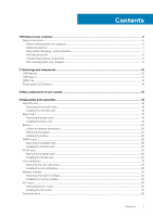
Safety instructions...6 Before working inside your computer...6 Safety precautions...7 Electrostatic discharge-ESD protection...7 ESD field service kit ...8 the memory module...34 DC-in port...35 Removing the DC-in port...35 Installing the DC-in port...37 Solid state drive...39 Contents 3 - Dell Latitude 5400 | Service Manual - Page 4
Removing the M.2 SSD...39 Installing the M.2 SSD...40 Solid state drive bracket...41 Removing the solid state drive bracket...41 Installing the solid state drive bracket...42 Inner frame...43 Removing the inner frame...43 Installing the inner frame...45 SmartCard reader...47 Removing the SmartCard - Dell Latitude 5400 | Service Manual - Page 5
back cover assembly...104 Replacing the display back cover...104 Palmrest assembly...105 Replacing the palmrest and keyboard assembly...105 5 Troubleshooting...108 Enhanced Pre-Boot System Assessment (ePSA) diagnostics 108 Running the ePSA diagnostics...108 System diagnostic lights...108 WiFi power - Dell Latitude 5400 | Service Manual - Page 6
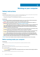
only perform troubleshooting and simple repairs as authorized in your product documentation, or as directed by the online or telephone service and support team. Damage due to servicing that is not authorized by Dell is not covered by your warranty. Read and follow the safety instructions that came - Dell Latitude 5400 | Service Manual - Page 7
disassembly instructions. electrocuted. Standby power Dell products with standby power through the use of a field service electrostatic discharge (ESD) kit. When obvious, such as intermittent problems or a shortened product of damage to recognize and troubleshoot is the intermittent (also called - Dell Latitude 5400 | Service Manual - Page 8
service technicians use the traditional wired ESD grounding wrist strap and protective anti-static mat at all times when servicing Dell stable base, and point your toes out. 2. Tighten stomach muscles. Abdominal muscles support your spine when you lift, offsetting the force of the load. 3. Lift with - Dell Latitude 5400 | Service Manual - Page 9
4. Keep the load close. The closer it is to your spine, the less force it exerts on your back. 5. Keep your back upright, whether lifting or setting down the load. Do not add the weight of your body to the load. Avoid twisting your body and back. 6. Follow the same techniques in reverse to set the - Dell Latitude 5400 | Service Manual - Page 10
connection between host computers and peripheral devices like mice, keyboards, external drivers, and printers. Let's take a quick look on the USB evolution devices • New power management features • Full-duplex data transfers and support for new transfer types • Backward USB 2.0 compatibility • New - Dell Latitude 5400 | Service Manual - Page 11
• Portable USB 3.0/USB 3.1 Gen 1 Hard Drives • USB 3.0/USB 3.1 Gen 1 Drive Docks & Adapters • USB 3.0/USB 3.1 Gen 1 Flash Drives & Readers • USB 3.0/USB 3.1 tiny physical connector. The connector itself can support various exciting new USB standards like USB 3.1 and USB power delivery - Dell Latitude 5400 | Service Manual - Page 12
of power - that'll charge your phone, but that's about it. A laptop might require up to 60 watts, for example. The USB Power Delivery specification ups any dock, display or data device like an external hard drive. Thunderbolt 3 uses a USB Type-C connector/port to connect to supported peripherals. - Dell Latitude 5400 | Service Manual - Page 13
1.4a This topic explains the HDMI 1.4a and its features along with the advantages. HDMI (High-Definition Multimedia Interface) is an industry-supported, uncompressed, all-digital audio/video interface. HDMI provides an interface between any compatible digital audio/video source, such as a DVD player - Dell Latitude 5400 | Service Manual - Page 14
, and confusion of multiple cables currently used in A/V systems • HDMI supports communication between the video source (such as a DVD player) and the DTV, enabling new functionality Power button LED behavior On certain Dell Latitude systems, the power button LED is used to provide an indication of - Dell Latitude 5400 | Service Manual - Page 15
Mute LED: • When activated (muted), the mic mute LED on the F4 Key should illuminate WHITE. • RJ45 LEDs: • Table 2. LED on either side of RJ45 port Link speed indicator (LHS) Activity indicator (RHS) Green Amber Technology and components 15 - Dell Latitude 5400 | Service Manual - Page 16
3 Major components of your system 1. Base cover 2. Heatsink 16 Major components of your system - Dell Latitude 5400 | Service Manual - Page 17
3. DC-in port 4. System fan 5. System board 6. Battery 7. Inner frame 8. Speakers 9. SmartCard reader 10. Touchpad button board 11. LED board 12. Palmrest assembly 13. Display assembly 14. Solid-state drive 15. Memory module 16. WLAN card 17. Coin-cell battery NOTE: Dell provides a list of - Dell Latitude 5400 | Service Manual - Page 18
4 Disassembly and reassembly MicroSD card Removing the microSD card Prerequisites 1. Follow the procedure in Before working inside your computer. Steps 1. Push the microSD card to release it from the computer [1]. 2. Slide the microSD card out of the computer [2]. Installing the microSD card Steps - Dell Latitude 5400 | Service Manual - Page 19
3. Follow the procedures in After working inside your computer. Base cover Removing the base cover Prerequisites 1. Follow the procedure in before working inside your computer 2. Remove the microSD card. Steps 1. Loosen the eight captive screws [1]. Disassembly and reassembly 19 - Dell Latitude 5400 | Service Manual - Page 20
2. Using a plastic scribe [1], pry the base cover from the top-left corner and continue to work on the sides to open the base cover [2]. 20 Disassembly and reassembly - Dell Latitude 5400 | Service Manual - Page 21
3. Lift and remove the base cover away from the computer. Installing the base cover Steps 1. Align and place the base cover on the computer. Disassembly and reassembly 21 - Dell Latitude 5400 | Service Manual - Page 22
2. Press the edges and sides of the base cover until it snaps into place. 22 Disassembly and reassembly - Dell Latitude 5400 | Service Manual - Page 23
3. Tighten the eight captive screws to secure the base cover to the computer. Disassembly and reassembly 23 - Dell Latitude 5400 | Service Manual - Page 24
to pry on or against the battery. • Ensure any screws during the servicing of this product are not lost or misplaced, to prevent accidental puncture or damage Dell technical support for assistance. See www.dell.com/contactdell. • Always purchase genuine batteries from www.dell.com or authorized Dell - Dell Latitude 5400 | Service Manual - Page 25
2. Loosen the single captive screw that secures the battery to the palmrest [1]. 3. Slide the battery inward and lift the battery away from the palmrest [2]. Disassembly and reassembly 25 - Dell Latitude 5400 | Service Manual - Page 26
Installing the battery Steps 1. Align and slide the battery on the palmrest [1]. 2. Tighten the single captive screw to secure the battery to the palmrest [2]. 26 Disassembly and reassembly - Dell Latitude 5400 | Service Manual - Page 27
3. Connect the battery cable to the connector on the system board. Disassembly and reassembly 27 - Dell Latitude 5400 | Service Manual - Page 28
Next steps 1. Replace the base cover. 2. Replace the microSD card. 3. Follow the procedure in after working inside your computer WWAN card Removing the WWAN card Prerequisites 1. Follow the procedure in before working inside your computer. 2. Remove the microSD card. 3. Remove the base cover. 4. - Dell Latitude 5400 | Service Manual - Page 29
Installing the WWAN card About this task CAUTION: To avoid damage to the WWAN card, do not place any cables under it. Steps 1. Insert the WWAN card into the connector on the system board [1]. 2. Connect the WWAN antenna cables to the connectors on the WWAN card [2]. 3. Place the WWAN card bracket to - Dell Latitude 5400 | Service Manual - Page 30
Installing the WLAN card About this task CAUTION: To avoid damage to the WLAN card, do not place any cables under it. Steps 1. Insert the WLAN card into the connector on the system board [1]. 2. Connect the WLAN antenna cables to the connectors on the WLAN card [2]. 3. Place the WLAN card bracket to - Dell Latitude 5400 | Service Manual - Page 31
Next steps 1. Replace the battery. 2. Replace the base cover. 3. Replace the microSD card. 4. Follow the procedure in after working inside your computer. Coin-cell battery Removing the coin-cell battery Prerequisites 1. Follow the procedure in before working inside your computer. 2. Remove the - Dell Latitude 5400 | Service Manual - Page 32
Installing the coin-cell battery Steps 1. Place the coin cell on the system board [1]. 2. Connect the coin cell battery cable to the connector on the system board [2]. 32 Disassembly and reassembly - Dell Latitude 5400 | Service Manual - Page 33
Next steps 1. Replace the battery. 2. Replace the base cover. 3. Replace the microSD card. 4. Follow the procedure in after working inside your computer. Memory modules Removing the memory module Prerequisites 1. Follow the procedure in before working inside your computer. 2. Remove the microSD card - Dell Latitude 5400 | Service Manual - Page 34
Installing the memory module Steps 1. Align the notch on the memory module with the tab on the memory-module slot. 2. Slide the memory module firmly into the slot at an angle [1]. 3. Press the memory module down until the clips secure it [2]. NOTE: If you do not hear the click, remove the memory - Dell Latitude 5400 | Service Manual - Page 35
. 2. Replace the base cover. 3. Replace the microSD card. 4. Follow the procedure in after working inside your computer. DC-in port Removing the DC-in port Prerequisites 1. Follow the procedure in before working inside your computer. 2. Remove the microSD card. 3. Remove the base cover. 4. Remove - Dell Latitude 5400 | Service Manual - Page 36
3. Disconnect the DC-in port cable from the connector on the system board and remove the DC-in port from the computer [1, 2]. 36 Disassembly and reassembly - Dell Latitude 5400 | Service Manual - Page 37
Installing the DC-in port Steps 1. Place the DC-in port to its slot on the computer [1]. 2. Connect the DC-in port cable to the connector on the system board [2]. Disassembly and reassembly 37 - Dell Latitude 5400 | Service Manual - Page 38
3. Place the Type-C bracket on its slot on the computer [1]. 4. Replace the two (M2x5) screws to secure the Type-C bracket to the palmrest [2]. 38 Disassembly and reassembly - Dell Latitude 5400 | Service Manual - Page 39
computer. 2. Remove the microSD card. 3. Remove the base cover. 4. Remove the battery. Steps 1. Remove the two (M2x3) screws that secure the M.2 SSD support bracket to the palmrest [1]. 2. Slightly turn and remove the SSD support bracket from the M.2 SSD slot [2]. Disassembly and reassembly 39 - Dell Latitude 5400 | Service Manual - Page 40
of the SSD thermal plate. Installing the M.2 SSD Steps 1. Place the M.2 SSD into the slot on the palmrest [1]. 2. Align and place the SSD support bracket above the M.2 SSD [2]. 3. Replace the two (M2x3) screws to secure the SSD support bracket to the palmrest [3]. 40 Disassembly and reassembly - Dell Latitude 5400 | Service Manual - Page 41
Next steps 1. Replace the battery. 2. Replace the base cover. 3. Replace the microSD card. 4. Follow the procedure in after working inside your computer. Solid state drive bracket Removing the solid state drive bracket Prerequisites 1. Follow the procedure in before working inside your computer. 2. - Dell Latitude 5400 | Service Manual - Page 42
Installing the solid state drive bracket Steps 1. Align the bracket and insert it into the slot on the palmrest [1]. 2. Replace the single (M2x3) screw to secure the bracket to the palmrest [2]. 42 Disassembly and reassembly - Dell Latitude 5400 | Service Manual - Page 43
Next steps 1. Replace the M.2 SSD. 2. Replace the battery. 3. Replace the base cover. 4. Replace the microSD card. 5. Follow the procedure in after working inside your computer. Inner frame Removing the inner frame Prerequisites 1. Follow the procedure in before working inside your computer. 2. - Dell Latitude 5400 | Service Manual - Page 44
2. Remove the five (M2x5) screws that secure the inner frame to the system board [1]. 3. Remove the six (M2x3) screws that secure the inner frame to the system chassis [2]. 4. Lift the inner frame away from the system chassis [3]. 44 Disassembly and reassembly - Dell Latitude 5400 | Service Manual - Page 45
Installing the inner frame Steps 1. Align and place the inner frame on the system chassis [1]. 2. Replace the six (M2x3) screws to secure the inner frame to the system chassis [2]. 3. Replace the five (M2x5) screws to secure the inner frame to the system board [3]. Disassembly and reassembly 45 - Dell Latitude 5400 | Service Manual - Page 46
4. Reroute the WLAN antenna cables. 46 Disassembly and reassembly - Dell Latitude 5400 | Service Manual - Page 47
Next steps 1. Replace the M.2 SSD holder. 2. Replace the M.2 SSD. 3. Replace the WLAN card. 4. Replace the battery. 5. Replace the base cover. 6. Replace the microSD card. 7. Follow the procedure in after working inside your computer. SmartCard reader Removing the SmartCard reader Prerequisites 1. - Dell Latitude 5400 | Service Manual - Page 48
3. Remove the three (M2x3) screws that secure the smartcard reader to the palmrest [1]. 4. Lift the smartcard reader board away from the palmrest [2]. 48 Disassembly and reassembly - Dell Latitude 5400 | Service Manual - Page 49
Installing the SmartCard reader Steps 1. Place the smart card reader board on the palmrest [1]. 2. Replace the three (M2x3) screws to secure the smartcard reader on the palmrest [2]. Disassembly and reassembly 49 - Dell Latitude 5400 | Service Manual - Page 50
3. Connect the smartcard reader FFC to the connector on the USH board [1]. 4. Adhere the smartcard FFC to the palmrest [2]. 50 Disassembly and reassembly - Dell Latitude 5400 | Service Manual - Page 51
Next steps 1. Replace the inner frame. 2. Replace the WLAN card. 3. Replace the battery. 4. Replace the base cover. 5. Replace the microSD card. 6. Follow the procedure in after working inside your computer. Touchpad buttons Removing the touchpad button board Prerequisites 1. Follow the procedure in - Dell Latitude 5400 | Service Manual - Page 52
3. Open the latch and disconnect the touchpad button board cable from the connector on the touchpad board [1, 2]. 52 Disassembly and reassembly - Dell Latitude 5400 | Service Manual - Page 53
4. Remove the two (M2x3) screws that secure the touchpad button bracket to the palmrest [1]. 5. Lift the touchpad button board bracket away from the computer [2]. Installing the touchpad button board Steps 1. Place the touchpad button board into the slot on the palmrest [1]. 2. Replace the two ( - Dell Latitude 5400 | Service Manual - Page 54
3. Connect the touchpad button board cable to the connector on the touchpad board [1, 2]. 54 Disassembly and reassembly - Dell Latitude 5400 | Service Manual - Page 55
4. Connect the Smartcard reader Flexible Flat Cable (FFC) to the USH board [1]. 5. Adhere the FFC on the palmrest [2]. Next steps 1. Replace the speaker. 2. Replace the battery. 3. Replace the base cover. 4. Replace the microSD card. 5. Follow the procedure in after working inside your computer. - Dell Latitude 5400 | Service Manual - Page 56
3. Remove the single (M2x3) screw that secures LED board to the palmrest [1]. 4. Lift the LED board away from the computer [2]. 56 Disassembly and reassembly - Dell Latitude 5400 | Service Manual - Page 57
Installing the LED board Steps 1. Place the LED board and align the screw hole on the LED board with the screw hole on the palmrest [1]. 2. Replace the single (M2x3) screw to secure the LED board to the palmrest [2]. Disassembly and reassembly 57 - Dell Latitude 5400 | Service Manual - Page 58
3. Connect the LED board cable to the connector on the system board and route the LED board cable [1, 2]. 58 Disassembly and reassembly - Dell Latitude 5400 | Service Manual - Page 59
Next steps 1. Replace the battery. 2. Replace the base cover. 3. Replace the microSD card. 4. Follow the procedure in after working inside your computer. Speakers Removing the speakers Prerequisites 1. Follow the procedure in before working inside your computer. 2. Remove the microSD card. 3. Remove - Dell Latitude 5400 | Service Manual - Page 60
Installing the speakers Steps 1. Using the alignment posts and rubber grommets, place the speakers in the slots on the palmrest. 2. Route the speaker cable through the routing guides. 60 Disassembly and reassembly - Dell Latitude 5400 | Service Manual - Page 61
3. Affix the adhesive tape to secure speaker cable to the palmrest [1]. 4. Connect the speaker cable to the connector on the system board [2, 3]. Disassembly and reassembly 61 - Dell Latitude 5400 | Service Manual - Page 62
Next steps 1. Replace the battery. 2. Replace the base cover. 3. Replace the microSD card. 4. Follow the procedure in after working inside your computer. Heatsink assembly Removing the heatsink assembly Prerequisites 1. Follow the procedure in before working inside your computer. 2. Remove the - Dell Latitude 5400 | Service Manual - Page 63
2. Remove the six (M2x3) screws that secure the heatsink assembly to the system board [1]. NOTE: Remove the screws in the order of the callout numbers [1, 2, 3, 4, 5, 6] as indicated on the heatsink. 3. Remove the two (M2x3) screws that secure the fan section of heatsink to the system board and lift - Dell Latitude 5400 | Service Manual - Page 64
Installing the heatsink assembly Steps 1. Place the heatsink assembly on the system board and align the screw holes on the heatsink with the screw holes on the system board [1]. 2. Replace the two (M2x3) screws that secure the fan section of the heatsink assembly to the system board. 3. In - Dell Latitude 5400 | Service Manual - Page 65
4. Connect the system fan cable from the connector on the system board. Disassembly and reassembly 65 - Dell Latitude 5400 | Service Manual - Page 66
Next steps 1. Replace the inner frame. 2. Replace the battery. 3. Replace the base cover. 4. Replace the microSD card. 5. Follow the procedure in after working inside your computer. System board Removing the system board Prerequisites 1. Follow the procedure in before working inside your computer. - Dell Latitude 5400 | Service Manual - Page 67
board cable [2]. c) USH FFC [3]. d) Touchpad FFC [4]. 2. Remove the single (M2x3) screw that secures the fingerprint support bracket to the system board [1]. 3. Lift the fingerprint support bracket away from the computer [2]. 4. Disconnect the fingerprint port [3]. Disassembly and reassembly 67 - Dell Latitude 5400 | Service Manual - Page 68
5. Peel the adhesive tape on the eDP cable that is connected to the system board [1]. 6. Remove the two (M2x3) screws that secure the eDP bracket to the system board [2]. 7. Remove the eDP bracket away from the computer [3]. 8. Lift the latch and disconnect the eDP cable from the connector on the - Dell Latitude 5400 | Service Manual - Page 69
10. Remove the two (M2x3) screws that secure the system board to the palmrest [1]. 11. Lift the system board away from the computer [2]. Disassembly and reassembly 69 - Dell Latitude 5400 | Service Manual - Page 70
Installing the system board Steps 1. Align and place the system board on the palmrest [1]. 2. Replace the two (M2x3) screws to secure the system board to the palmrest [2]. 70 Disassembly and reassembly - Dell Latitude 5400 | Service Manual - Page 71
Connect the cable to the connector on the system board [1]. 4. Connect the eDP cable to the connector on the system board [2]. 5. Place the eDP support bracket above the eDP connector [3]. 6. Replace the two (M2x3) screws to secure the eDP bracket to the system board [4]. 7. Adhere the adhesive tape - Dell Latitude 5400 | Service Manual - Page 72
8. Connect the fingerprint cable to the connector on the system board [1]. 9. Place the fingerprint support bracket [2]. 10. Replace the single (M2x3) screw to secure the fingerprint support bracket to the system board [3]. 72 Disassembly and reassembly - Dell Latitude 5400 | Service Manual - Page 73
11. Connect the following cables to the system board: a) Speaker cable [1]. b) LED board cable [2]. c) USH FFC [3] d) Touchpad FFC [4]. Disassembly and reassembly 73 - Dell Latitude 5400 | Service Manual - Page 74
Next steps 1. Replace the heatsink assembly. 2. Replace the M.2 SSD. 3. Replace the DC-in. 4. Replace the coin cell battery. 5. Replace the WLAN card. 6. Replace the memory module. 7. Replace the battery. 8. Replace the base cover. 9. Replace the microSD card. 10. Follow the procedure in after - Dell Latitude 5400 | Service Manual - Page 75
4. Remove the battery. 5. Remove the speaker. 6. Remove the memory module. 7. Remove the DC-in . 8. Remove the WLAN card. 9. Remove the system board. NOTE: System board can be removed with heatsink assembly attached. 10. Remove the coin cell battery. Steps 1. Lift the latch and disconnect the - Dell Latitude 5400 | Service Manual - Page 76
Installing the keyboard Steps 1. Align and place the keyboard on the palmrest [1]. 2. Replace the 18 (M2x2.5) screws to secure the keyboard to the palmrest [2]. 76 Disassembly and reassembly - Dell Latitude 5400 | Service Manual - Page 77
3. Connect the backlit cable and the keyboard cable to the connectors on the touchpad. Disassembly and reassembly 77 - Dell Latitude 5400 | Service Manual - Page 78
Next steps 1. Replace the coin cell battery. 2. Replace the system board. NOTE: System board can be replaced with heatsink assembly attached. 3. Replace the WLAN card. 4. Replace the DC-in. 5. Replace the memory module. 6. Replace the speaker. 7. Replace the battery. 8. Replace the base cover. 9. - Dell Latitude 5400 | Service Manual - Page 79
7. Remove the DC-in . 8. Remove the WLAN card. 9. Remove the system board. NOTE: System board can be removed with heatsink assembly attached. 10. Remove the coin cell battery. 11. Remove the keyboard. Steps 1. Remove the six (M2x2) screws that secure the keyboard to the keyboard bracket [1]. 2. - Dell Latitude 5400 | Service Manual - Page 80
Next steps 1. Replace the keyboard. 2. Replace the coin cell battery. 3. Replace the system board. NOTE: System board can be replaced with heatsink assembly attached. 4. Replace the WLAN card. 5. Replace the DC-in. 6. Replace the memory module. 7. Replace the speaker. 8. Replace the battery. 9. - Dell Latitude 5400 | Service Manual - Page 81
4. Remove the battery. 5. Remove the speaker. 6. Remove the memory module. 7. Remove the DC-in . 8. Remove the WLAN card. 9. Remove the system board. NOTE: System board can be removed with heatsink assembly attached. 10. Remove the coin cell battery. 11. Remove the keyboard. Steps 1. Remove the two - Dell Latitude 5400 | Service Manual - Page 82
Next steps 1. Replace the keyboard. 2. Replace the coin cell battery. 3. Replace the system board. NOTE: System board can be replaced with heatsink assembly attached. 4. Replace the WLAN card. 5. Replace the DC-in. 6. Replace the memory module. 7. Replace the speaker. 8. Replace the battery. 9. - Dell Latitude 5400 | Service Manual - Page 83
Steps 1. Unroute the wireless antenna from the routing guides on the system board [1]. 2. Peel off the tape securing the eDP cable bracket [2]. 3. Remove the two (M2x3) screws that secures the eDP cable bracket to - Dell Latitude 5400 | Service Manual - Page 84
7. Remove the four (M2.5x5) screws that secures the display assembly to the system chassis [1]. 8. Remove the display assembly from the system [2]. 84 Disassembly and reassembly - Dell Latitude 5400 | Service Manual - Page 85
Installing the display assembly About this task NOTE: Ensure that the hinges are opened to the maximum before replacing the display assembly on the palmrest. Steps 1. Align and place the system chassis under the hinges of the display assembly [1]. 2. Replace the four (M2.5x5) screws that secure the - Dell Latitude 5400 | Service Manual - Page 86
3. Seat the system chassis on the display assembly. 86 Disassembly and reassembly - Dell Latitude 5400 | Service Manual - Page 87
4. Reroute the wireless antenna through the routing guides on the system board [1]. 5. Connect the cable to the connector on the system board [2]. 6. Connect the eDP cable to the eDP connector on the system - Dell Latitude 5400 | Service Manual - Page 88
Next steps 1. Replace the WLAN card. 2. Replace the battery. 3. Replace the base cover. 4. Replace the microSD card. 5. Follow the procedure in after working inside your computer. Display bezel Removing display bezel Prerequisites 1. Follow the procedure in before working inside your computer. 2. - Dell Latitude 5400 | Service Manual - Page 89
: When prying open the display bezel, ensure to pry along the outside edge of the display bezel using your hands or plastic scribes-using a screw driver or other sharp objects may damage the display cover. Carefully pry open the inside edge of the display bezel and then pry open the inside - Dell Latitude 5400 | Service Manual - Page 90
Installing the display bezel Steps Align the display bezel with the display assembly, and then gently snap the display bezel into place. 90 Disassembly and reassembly - Dell Latitude 5400 | Service Manual - Page 91
Disassembly and reassembly 91 - Dell Latitude 5400 | Service Manual - Page 92
Next steps 1. Replace the display assembly. 2. Replace the battery. 3. Replace the base cover. 4. Replace the microSD card. 5. Follow the procedure in after working inside your computer. Display panel Removing display panel Prerequisites 1. Follow the procedure in before working inside your computer - Dell Latitude 5400 | Service Manual - Page 93
2. Peel the conductive tape [1] on the display cable connector. 3. Remove the adhesive strip that secures the display cable connector [2]. 4. Lift the latch and disconnect the display cable from the connector on the display panel [3, 4]. NOTE: Do not pull and release the Stretch (SR) Tapes from the - Dell Latitude 5400 | Service Manual - Page 94
94 Disassembly and reassembly - Dell Latitude 5400 | Service Manual - Page 95
Installing display panel Steps 1. Connect the display cable to the connector and close the latch [1, 2]. 2. Adhere the adhesive strip to secure the display cable connector [3]. 3. Adhere the conductive tape to secure the display cable connector [4]. 4. NOTE: LCD Panel comes with two (L+R) brackets - Dell Latitude 5400 | Service Manual - Page 96
Next steps 1. Replace the display hinges. 2. Replace the hinge caps. 3. Replace the display bezel. 4. Replace the display assembly. 5. Replace the battery. 6. Replace the base cover. 7. Replace the microSD card. 8. Follow the procedure in after working inside your computer. Camera Removing camera - Dell Latitude 5400 | Service Manual - Page 97
8. Remove the display hinges. 9. Remove the display panel. Steps 1. Peel the two conductive tape that secures the camera in place [1]. 2. Carefully pry and lift the camera module from the display back cover [2]. 3. Disconnect the camera cable from the connector on the camera module [3]. Installing - Dell Latitude 5400 | Service Manual - Page 98
Next steps 1. Replace the display panel. 2. Replace the display hinges. 3. Replace the hinge caps. 4. Replace the display bezel. 5. Replace the display assembly. 6. Replace the battery. 7. Replace the base cover. 8. Replace the microSD card. 9. Follow the procedure in after working inside your - Dell Latitude 5400 | Service Manual - Page 99
Steps 1. Remove the two (M2x3) screws that secure the hinge caps to the chassis [1]. 2. Pinch the hinge caps to release the hinge caps from the ribs on the display back cover then slide inwards to remove the hinge caps from the display hinge [2]. Installing hinge caps Steps 1. Place the hinge caps - Dell Latitude 5400 | Service Manual - Page 100
Next steps 1. Replace the display bezel. 2. Replace the display assembly. 3. Replace the battery. 4. Replace the base cover. 5. Replace the microSD card. 6. Follow the procedure in after working inside your computer. Display hinges Removing display hinge Prerequisites 1. Follow the procedure in - Dell Latitude 5400 | Service Manual - Page 101
Steps 1. Remove the four (M2.5x3) screws that secure the display hinge to the display assembly [1]. 2. Remove the display hinges from the display back cover [2]. Installing display hinge Steps 1. Place the display hinge on the display assembly. 2. Replace the four (M2.5x3) screws to secure the - Dell Latitude 5400 | Service Manual - Page 102
Next steps 1. Replace the hinge caps. 2. Replace the display bezel. 3. Replace the display assembly. 4. Replace the battery. 5. Replace the base cover. 6. Replace the microSD card. 7. Follow the procedure in after working inside your computer. Display (eDP) cable Removing display cable Prerequisites - Dell Latitude 5400 | Service Manual - Page 103
9. Remove the display panel. 10. Remove the camera. Steps Peel the conductive tape and unroute the display cable to release it from adhesive and lift the display cable from the display back cover. Installing display cable Steps 1. Adhere the display cable to the display back cover. 2. Adhere the - Dell Latitude 5400 | Service Manual - Page 104
Next steps 1. Replace the camera. 2. Replace the display panel. 3. Replace the display hinges. 4. Replace the hinge caps. 5. Replace the display bezel. 6. Replace the display assembly. 7. Replace the battery. 8. Replace the base cover. 9. Replace the microSD card. 10. Follow the procedure in after - Dell Latitude 5400 | Service Manual - Page 105
10. Remove the camera. 11. Remove the display cable. About this task After performing the preceding steps, you are left with the display back cover. Next steps 1. Replace the display cable. 2. Replace the camera. 3. Replace the display panel. 4. Replace the display hinges. 5. Replace the hinge caps. - Dell Latitude 5400 | Service Manual - Page 106
3. Remove the base cover. 4. Remove the battery. 5. Remove the speaker. 6. Remove the memory module. 7. Remove the DC-in . 8. Remove the WLAN card. 9. Remove the system board. NOTE: System board can be removed with heatsink assembly attached. 10. Remove the coin cell battery. 11. Remove the keyboard - Dell Latitude 5400 | Service Manual - Page 107
11. Replace the microSD card. 12. Follow the procedure in after working inside your computer. Disassembly and reassembly 107 - Dell Latitude 5400 | Service Manual - Page 108
Troubleshooting successfully • View error messages that inform you of problems encountered during testing NOTE: Some tests for specific devices are displayed. Note the error code and validation number and contact Dell. System diagnostic lights Battery-status light Indicates the power and battery- - Dell Latitude 5400 | Service Manual - Page 109
problems. Table 3. LED codes Diagnostic light codes 2,1 2,2 2,3 2,4 2,5 2,6 2,7 2,8 3,1 3,2 3,3 3,4 3,5 3,6 3,7 Problem description . The following procedure provides the instructions on how to conduct a WiFi power cycle: NOTE: Some ISPs (Internet Service Providers) provide a modem/router - Dell Latitude 5400 | Service Manual - Page 110
. Availability varies by country and product, and some services may not be available in your area. To contact Dell for sales, technical support, or customer service issues: Steps 1. Go to Dell.com/support. 2. Select your support category. 3. Verify your country or region in the Choose a Country
-
 1
1 -
 2
2 -
 3
3 -
 4
4 -
 5
5 -
 6
6 -
 7
7 -
8
-
9
-
10
-
11
-
12
-
13
-
14
-
15
-
16
-
17
-
18
-
19
-
20
-
21
-
22
-
23
-
24
-
25
-
26
-
27
-
28
-
29
-
30
-
31
-
32
-
33
-
34
-
35
-
36
-
37
-
38
-
39
-
40
-
41
-
42
-
43
-
44
-
45
-
46
-
47
-
48
-
49
-
50
-
51
-
52
-
53
-
54
-
55
-
56
-
57
-
58
-
59
-
60
-
61
-
62
-
63
-
64
-
65
-
66
-
67
-
68
-
69
-
70
-
71
-
72
-
73
-
74
-
75
-
76
-
77
-
78
-
79
-
80
-
81
-
82
-
83
-
84
-
85
-
86
-
87
-
88
-
89
-
90
-
91
-
92
-
93
-
94
-
95
-
96
-
97
-
98
-
99
-
100
-
101
-
102
-
103
-
104
-
105
-
106
-
107
-
108
-
109
-
110
 |
 |

Dell Latitude 5400
Service Manual
Regulatory Model: P98G
Regulatory Type: P98G001