2010 Yamaha Motorsports Grizzly 700 4x4 EPS SE Owners Manual - Page 137
2010 Yamaha Motorsports Grizzly 700 4x4 EPS SE Manual

Page 137 highlights
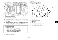
EBU27751 1 Replacing a fuse 2 1. Positive battery lead (red) 2. Negative battery lead (black) 1. 2. 3. 4. 5. 6. Fuse box Main/EPS spare fuse Main fuse EPS fuse Fuel injection system spare fuse Fuel injection system fuse 3. Install the battery holding plate by installing the nuts. 4. Install the front carrier by installing the bolts and tightening them to the specified torques. Tightening torques: Carrier bolt (top): 26 Nm (2.6 m·kgf, 19 ft·lbf) Carrier bolt (under the fenders): 7 Nm (0.7 m·kgf, 5.1 ft·lbf) 5. Install the panel. 8 8-57
-
 1
1 -
2
-
3
-
4
-
5
-
6
-
7
-
8
-
9
-
10
-
11
-
12
-
13
-
14
-
15
-
16
-
17
-
18
-
19
-
20
-
21
-
22
-
23
-
24
-
25
-
26
-
27
-
28
-
29
-
30
-
31
-
32
-
33
-
34
-
35
-
36
-
37
-
38
-
39
-
40
-
41
-
42
-
43
-
44
-
45
-
46
-
47
-
48
-
49
-
50
-
51
-
52
-
53
-
54
-
55
-
56
-
57
-
58
-
59
-
60
-
61
-
62
-
63
-
64
-
65
-
66
-
67
-
68
-
69
-
70
-
71
-
72
-
73
-
74
-
75
-
76
-
77
-
78
-
79
-
80
-
81
-
82
-
83
-
84
-
85
-
86
-
87
-
88
-
89
-
90
-
91
-
92
-
93
-
94
-
95
-
96
-
97
-
98
-
99
-
100
-
101
-
102
-
103
-
104
-
105
-
106
-
107
-
108
-
109
-
110
-
111
-
112
-
113
-
114
-
115
-
116
-
117
-
118
-
119
-
120
-
121
-
122
-
123
-
124
-
125
-
126
-
127
-
128
-
129
-
130
-
131
-
 132
132 -
 133
133 -
 134
134 -
 135
135 -
 136
136 -
 137
137 -
 138
138 -
 139
139 -
 140
140 -
 141
141 -
 142
142 -
143
-
144
-
145
-
146
-
147
-
148
-
149
-
150
-
151
-
152
-
153
-
154
-
155
-
156
-
157
-
158
-
159
-
160
-
161
-
162
-
163
-
164
-
165
-
166
-
167
-
168
-
169
-
170
 |
 |

8-57
8
3. Install the battery holding plate by installing
the nuts.
4.
Install the front carrier by installing the bolts
and tightening them to the specified torques.
5.
Install the panel.
EBU27751
Replacing a fuse
1.
Positive battery lead (red)
2.
Negative battery lead (black)
Tightening torques:
Carrier bolt (top):
26 Nm (2.6 m·kgf, 19 ft·lbf)
Carrier bolt (under the fenders):
7 Nm (0.7 m·kgf, 5.1 ft·lbf)
1
2
1.
Fuse box
2.
Main/EPS spare fuse
3.
Main fuse
4.
EPS fuse
5.
Fuel injection system spare fuse
6.
Fuel injection system fuse