Xerox 8550YDP User Guide - Page 92
Electronics Module, X-Axis Motor Assembly, Y-Axis Drive Motor Assembly, Apply Tape, Nose Cone,
 |
UPC - 095205022247
View all Xerox 8550YDP manuals
Add to My Manuals
Save this manual to your list of manuals |
Page 92 highlights
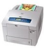
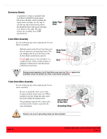
Electronics Module A small piece of tape is included with each Phaser 8500/8550 replacement Electronics Module. After installing the replacement assembly, use the tape to seal the top side of the housing where the Printhead Data Cable passes through it, as shown to the right. The tape ensures the assembly meets EMI specifications. Apply Tape Here X-Axis Motor Assembly Use the following tips when replacing the X-Axis Motor Assembly: ■ Slide the notch on the Nose Cone Gear over the rail extension on the printer frame. The rail stabilizes the Nose Cone Gear so the X-Axis Shaft can thread in and out. ■ Do not apply grease to the rail unless it is completely dry. A thin coating of grease is adequate to lubricate for smooth motion of the Nose Cone Gear. Nose Cone Gear Rail During normal operation, the X-Axis Motor runs very hot. Do not replace the assembly unless the printer has other x-axis failure symptoms. Y-Axis Drive Motor Assembly Use the following tips when replacing the Y-axis motor assembly: ■ Be sure to install the short screw in the location marked on the motor arm. When installed correctly, lifting the arm rotates the motor within the printer frame. ■ The grounding strap must be connected to avoid electronics failures caused by the static discharges. Install Short Screw Here Grounding Strap Failures can occur if grounding straps are disconnected. page 84 PHASER 8550, 8500, & 8400 SERVICE SECTION Version 1.0
-
 1
1 -
2
-
3
-
4
-
5
-
6
-
7
-
8
-
9
-
10
-
11
-
12
-
13
-
14
-
15
-
16
-
17
-
18
-
19
-
20
-
21
-
22
-
23
-
24
-
25
-
26
-
27
-
28
-
29
-
30
-
31
-
32
-
33
-
34
-
35
-
36
-
37
-
38
-
39
-
40
-
41
-
42
-
43
-
44
-
45
-
46
-
47
-
48
-
49
-
50
-
51
-
52
-
53
-
54
-
55
-
56
-
57
-
58
-
59
-
60
-
61
-
62
-
63
-
64
-
65
-
66
-
67
-
68
-
69
-
70
-
71
-
72
-
73
-
74
-
75
-
76
-
77
-
78
-
79
-
80
-
81
-
82
-
83
-
84
-
85
-
86
-
 87
87 -
 88
88 -
 89
89 -
 90
90 -
 91
91 -
 92
92 -
 93
93 -
 94
94 -
 95
95 -
 96
96 -
 97
97 -
98
-
99
-
100
-
101
-
102
-
103
-
104
 |
 |
