Xerox 8550YDP User Guide - Page 88
Pry Here To, Remove Cover, Right Side Cover Only, Post On, Exit Door, Mounting Pin
 |
UPC - 095205022247
View all Xerox 8550YDP manuals
Add to My Manuals
Save this manual to your list of manuals |
Page 88 highlights
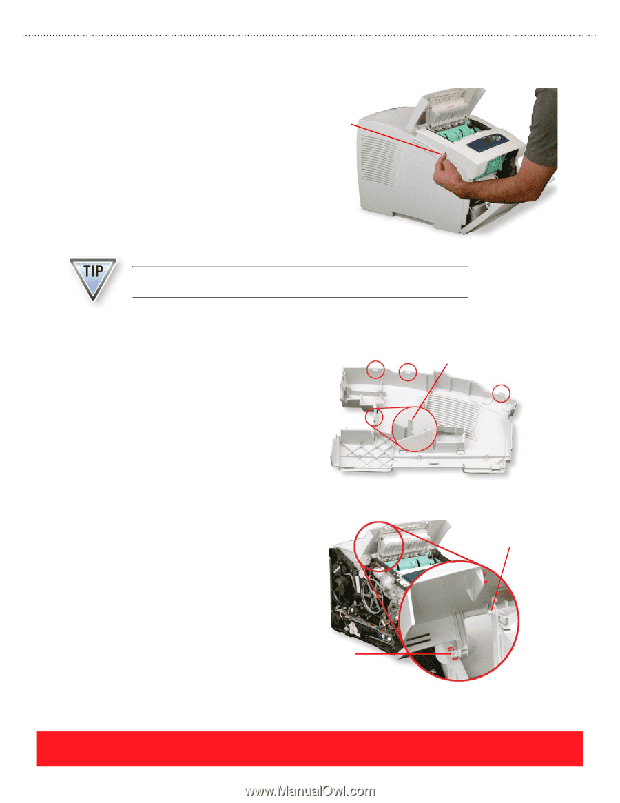
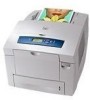
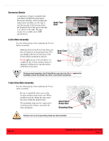
Control Panel Cover Use your fingers or a small screwdriver to pry up on the left side of the cover as shown to the right, and then pull it forward. After the cover is loose, press down on the Control Panel to release it from the cover. Pry Here To Remove Cover Keep the Control Panel attached so the printer will function after removing the Control Panel cover. Left & Right Side Covers Each side cover has latches along the top edge in the locations shown to the right. Release them by pulling up on the rounded area near the back of the printer and near the front cover. The right side cover has one more latch located next to the power cord receptacle. You may need to release this latch when removing the cover. Exit Cover Mounting pins located on each side of the exit cover are captured by the left and right side covers. Be sure to install the exit cover and position the pins into notches on the Ink Loader Assembly frame before installing the side covers. Also, make sure posts on each side of the exit door slide freely within the groove on the bottom of the exit cover. Mounting Pin Right Side Cover Only Post On Exit Door page 80 PHASER 8550, 8500, & 8400 SERVICE SECTION Version 1.0
-
 1
1 -
2
-
3
-
4
-
5
-
6
-
7
-
8
-
9
-
10
-
11
-
12
-
13
-
14
-
15
-
16
-
17
-
18
-
19
-
20
-
21
-
22
-
23
-
24
-
25
-
26
-
27
-
28
-
29
-
30
-
31
-
32
-
33
-
34
-
35
-
36
-
37
-
38
-
39
-
40
-
41
-
42
-
43
-
44
-
45
-
46
-
47
-
48
-
49
-
50
-
51
-
52
-
53
-
54
-
55
-
56
-
57
-
58
-
59
-
60
-
61
-
62
-
63
-
64
-
65
-
66
-
67
-
68
-
69
-
70
-
71
-
72
-
73
-
74
-
75
-
76
-
77
-
78
-
79
-
80
-
81
-
82
-
 83
83 -
 84
84 -
 85
85 -
 86
86 -
 87
87 -
 88
88 -
 89
89 -
 90
90 -
 91
91 -
 92
92 -
 93
93 -
94
-
95
-
96
-
97
-
98
-
99
-
100
-
101
-
102
-
103
-
104
 |
 |