Vivitar 285-HV User Guide - Page 4
Calculator, Sufficient, Light, Indicator
 |
View all Vivitar 285-HV manuals
Add to My Manuals
Save this manual to your list of manuals |
Page 4 highlights
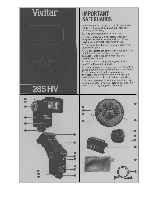
Mode Selector Dial The Mode Selector Dial (24) on the Van Sensor Module allows you to set the 285HV for manual operation or for automatic operation with four different f-stops on your camera lens. This provides you with a means for controlling the depth of field in your. photographs. Because the four f-stops vary with the speed of the film you are using, each automatic mode is assigned a color. The Mode Selector Dial may be set to any one of four auto positions: YELLOW-Utilizes the widest lens opening for relatively shallow depth of field and provides the greatest automatic operating range. Automatic operating range with Zoom/Bounce Head in NORM position: 6-60 feet (1.8-18.3 rrifeters). RED-Utilizes a medium lens opening for somewhat more depth of field. The automatic operating range is shortened accordingly. Automatic operating range with'Head in NORM position: 5-30 feet (1.5-9.1. meters). BLUE-Utlizes a smaller lens opening for greater depth of field. Automatic operating range withHead. in NORM position: 2-15 feet (07-4.4 meters). PURPLE-Utilizes the smallest lens opening for maximum depth of field. Automatic operating range with Head in NORM position: 2-11 feet (0.7-3.3 meters). For operating details, see the section "Shooting Automatically" and the chart of automatic f-stops and corresponding ranges at the rear of this manual. In addition to the four auto positions, the Mode Selector Dial has a manual position "M." When set in this position, your flash unit will provide maximum light output regardless orthe flashto-subject distance. Operating details are given in the "Shooting Manually" section of these instructions. To handle special situation needs, such as fill-in flash, multiple flash set-ups or for freezing high-speed action, your Vivitar 10 4. Select auto operating mode There are four colored wedges (23) with trailing range lines on the Calculator Dial. Each color represents an automatic operating mode which corresponds to an automatic f-stop. Each mode takes into account a combination of two things -the auto range and depth of field (greatest sharpness in front and back of subject). Which colored mode you select will depend on the combination you want. Select the auto mode you want. The Calculator Dial will give you the minimum and maximum auto range and correct f-stop setting for the auto moda you've selected. To determine operating ranger -f the selected mode, look on the dial and find the colored wedge of the mode and the range line that trails off from it. It looks like this: 4 The number at the end of the line is the closest distance from your subject that the flash can be properly used. The number in the center of the wedge is the longest distance. The number above the colored wedge is the f-stop number to set your camera lens to. If the colored wedges fall between two different f-stops, refer to the Automatic Operation Chart at rear of this manual in order to determine the best f-stop to use. Example: You're using ASA/ISO 100 (DIN 21) film with the Flash Zoom Head in the NORM position. You select the RED mode. Your flash range would be 5 to 30 feet (1.5 to 9.t meters) and the f-stop setting would be f4.0. (See photo A.) 5. Select desired zoom position. After you have set up the Calculator Dial with the Zoom/Bounce Head in the NORM position, you may wish to operate the flash unit with the Zoom/Bounce Head in the WIDE or TELE position. When the Zoom/Bounce Head is extended or retracted from the NORM position, the distance scale on the Calculator Dial will change position automatically. Example: With a setting of ISO/ASA 100 (DIN 21), when the Zoom/Bounce Head is set in the NORM position, the operating distance 'n the Red mode is 5-30 feet (1.5-9.1 m). When the 12 Model 285HV features a variable power system. With this system, you can reduce the light output from full power to 1/2, 1/4 or 1/16 power by setting the Mode Selector Dial in the corrspondingly marked position. For operating details, refer to the "Niari-Power" portion of the "Shooting Manually" section. Calculator Dial The Calculator Dial (4) is a convenient built-in guide for determining flash exposures. It is not electronically connected to the flash. After familiarizing yourself with the meanings of the numbers and colors, you will find the dial to be a very versatile tool. Under dim lighting conditions, press the Calculator Dial Light Button (11), and the dial is illuminated. Operation: 1. Set the Zoom/Bounce Flash Head to the NORM position. 2. Set the black arrow (19) of the Vert-Power Dial (inner ring of Calculator Dial) to the FULL position. (See photo A.) 3. Set the ASA/DIN film speed. To set the Calculator Dial for the ASA(ISO) or DIN number of the film you are using. turn the outer edge of the dial until the appropriate number on the ASA or DIN scale is opposite the white Film Speed Indicator Arrow (5). If the ASA or DIN number of your film is not on the Calculator Dial, use the film speed chart shown below to find the film speed location and align that speed with the white arrow. FILM SPEED SCALE DIN 27 26 25 24 23 22 21 20 19 18 17 16 15 ASA 400 320 250 200 160 125 100 80 64 50 40 32 25 Dial 400 I I I 160 I 100 I 64 I I I 25 11 head is extended to TELE, the operating range for the Red mode becomes 6-35 feet (1.8-10.6 m). See photographs A and E for comparison. Sufficient Light Indicator The Sufficient Light Indicator (10) on your Vivitar 285HV lets you know before you take a picture if the light output will be sufficient for a proper exposure. It may be used when shooting in any of the four automatic modes, and is especially helpful in bounce light situations normally'requiring complex exposure calculations. To test an exposure using the Sufficient Light Indicator: 1. Position your camera, flash, and subject just as you wish for the final picture. 2. Set the Mode Selector Dial on the Flash Sensor to the automatic mode color which matches the mode wedge color already selected on the Calculator Dial. 3. Set your camera lens to the f-stop indicated above that colored wedge on the Calculator Dial. 4. Switch on the flash unit. After the green Ready Light glows, fire the flash by pushing the Open Flash Button (1). If the flash exposure is adequate, the green Sufficient Light Indicator (10) will glow for about 2 seconds immediately after firing the flash. If it doesn't light up, do one of the following: Set your flash and camera to an automatic mode that uses a wider f-stop opening; or, decrease the flash-to-subject distance. NOTE: The Sufficient Light Indicator is for use in any of the four Automatic Modes and will not light if the Mode Selector Dial on the Sensor is set on manual "M" or if the Sensor is not connected to the flash. The Sufficient Light Indicator will, however, also light up when the Mode Selector is set to one of the fractional Van-Power positions. This is of NO SIGNIFICANCE and should be disregarded. 13
-
 1
1 -
 2
2 -
 3
3 -
 4
4 -
 5
5 -
 6
6 -
 7
7 -
 8
8
 |
 |
