Vivitar 285-HV User Guide - Page 3
Ready, Light, Battery, Saving, Circuit, Operation, Zoom/Bounce, Flash, Automatic
 |
View all Vivitar 285-HV manuals
Add to My Manuals
Save this manual to your list of manuals |
Page 3 highlights
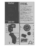
a few minutes before you resume firing. 2) The HVP-1 High Voltage Battery Pack - Also available from your Vivitar dealer, this unit utilizes disposable high voltage batteries or the rechargeable Vivitar FIB-510 battery to provide very fast recycle times and a greater number of flashes than that provided by the other battery power sources described above. 3) The Vivitar PPG-1 Power Pistol Grip - The PPG-1 Power Pistol Grip is a detachable pistol grip/flash holder for oftcamera use and can provide supplemental power for faster recycling arid more flashes. It uses four AA alkaline batteries, NiCads, or the special Vivitar NC-3 NiCad Pack. It has a 360° rotating shoe for added versatility. 4) The Vivitar SB-4 AC Adapter - This adapter allows you to use standard electrical outlets as an optional and economical power source. IMPORTANT NOTE: When using the HVP-1, PPG-1 or SB-4 power sources, four fresh AA alkalines or one properly charged NC-3 battery pack must be In the flash unit to operate the synchronization circuit. Ready Light The Vivitar 285HV is equipped wittta Ready Light (13) with a 3-stage operation: It glows red when the flash is at 1/2 power, glows green when the flash is at 3/4 power, and blinks alternately red and green when the Battery Saving Circuit is in operation and the unit is at full power. The new 285HV has a modified triggering circuit which allows you to fire the flash before the Ready Light goes on. But be aware that underexposures may result when the unit is fired before the Ready Light is on. 6 2. With batteries in the flash, slide the On-Oft Switch (12) to the RED "ON" position, or plug the optional SB-4 AC Adapter into both the flash AC Adapter Receptacle (17) and the wall outlet. NOTE: The flash's On-Off Switch must be in the "OFF' position when using the AC Adapter. Make sure there are batteries in the unit to work the synchronization circuit when using the SB-4. 3. When the green Ready Light glows, fire the flash using the Open Flash Button (1), allowing the Ready Light to glow 15 to 20 seconds first. After a sequence of 5 flashes, your capacitor will then be formed and you are ready to begin shooting. Thyristor Circuit Your Vivitar Model 285HV has a unique power conservation sytem called a thyristor circuit. In any of the four auto modes, this circuit saves the excess energy not needed for a proper exposure, threby providing very fast recycling time and a greater number of flashes per battery charge. The recycle time and the number of flashes per charge varies depending on the flash-to-subject distance and the auto mode used. As you move the flash closer to the subject, the 285HV recycles faster and is capable of providing more flashes per set of batteries. Zoom/Bounce Flash Head Zoom Position The Zoom/Bounce Flash Head (7) allows you to coordinate the field coverage of your flash with the field covered by your camera lens. Positions are marked on the Zoom Setting Indicator (8) for wide, normal and tele - equivalent to camera focal lengths of 35mm, 50/55mm and 105mm. Extend or retract the Zoom/Bounce Flash Head to the position which is closest to the focal length of the camera lens you are using. 8 Battery Saving Circuit Your flash unit has a built-in circuit that acts to significantly prolong battery life. When this circuit is in operation, the Ready Light will blink alternately red and green. Battery Operation Inserting Batteries 1. Set the Flash Head to the straight-ahead 0° position. Pushing with your thumb from the front of the unit, slide open the Battery Compartment Cover (3) and take out the Battery Holder (27). NOTE: There is a stop built into the cover to prevent it from coming all the way off the back. DO NOT FORCE THE COVER. 2. Insert four fresh 1.5 volt size AA alkaline batteries or NiCads, following the battery positioning marked on the Holder. 3. Insert the Holder into the battery compartment (align the square corner) and slide the Battery Compartment Cover closed. There are some simple procedures to follow for getting the most out of your flash and batteries, Always turn your unit off right after you've finished using it to prolong battery life. Also, when storing your flash for a period of time, remove the batteries, to prevent possible damage from battery corrosion. Replace the batteries it the red Ready Light fails to glow within 30 seconds. Forming the Capacitor When your flash is new or when it has not been used for a period of time, the capacitor loses some of its ability to store electricity. When this occurs, you can "form" the capacitor as follows: 1. Set the Mode Selector Dial (24) to the manual "M" position. 7 in addition, a 28mm Wide Angle Flash Lens (28) is included with your Model 285HV Flash. Insert the flash lens into the Lens/Filter Slot (6), with the tab on the lens at the bottom. The 28mm Flash Lens is designed to be used with the Zoom/Bounce Flash Head in the wide position. Bounce Angle The Model 285HV will tilt to any of five click positions (9) (0°, 45°, 60°, 75°, 90°), depending on the lighting you want to create. When the flash is set at the 45°, 60°, 75° or 90° position, you can bounce light off a reflective surface to create softer lighting. Automatic Operation Van Sensor Module Your Vivitar 285HV Electronic Flash is equipped with a removable Vari Sensor Module (26) that measures the light reflected from the subject and other reflective surfaces near the subject. This information is interpreted by a solid state computer in the sensor which programs the flash to automatically provide just the right amount of light required for a correct exposure. The practical advantage is that you don't have to change the f-stop on your camera lens when you move closer to a subject or farther away. As long as your subject is within the automatic operating range of the flash for that f-stop, the computer automatically makes the adjustment for you. . To remove the Vari Sensor Module from the flash, pull it straight out from the body of the flash. To mount the Module back on the flash, align the black ridge at the back of the Module with the groove in the Sensor Socket (2) and push the Module firmly into the flash. 9
-
 1
1 -
 2
2 -
 3
3 -
 4
4 -
 5
5 -
 6
6 -
 7
7 -
 8
8
 |
 |
