URC MRX-8 Owners Manual - Page 6
Rear Panel Descriptions
 |
View all URC MRX-8 manuals
Add to My Manuals
Save this manual to your list of manuals |
Page 6 highlights
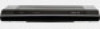
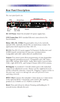
TOTAL CONTROL MRX-8 SYSTEM CONTROLLER Rear Panel Descriptions The rear panel ports are: LAN RS-232 Ports IR Outputs: #1-6 Reset DC 12V Power Relay: NO, NC, COM Sensors RFTX-1 DC 12V Power: Attach the included 12V power supply here. LAN Connection: RJ45 standard Ethernet connection to the local network. Relays (NO, NC, COM): Programmable relay to be normally opened (NO), normally closed (NC) or momentary contact. An application shall require less than 30V/.5A. RS-232: Two RS-232 ports support Tx(Transmit), Rx(Receive) and GND(Ground) connections for two-way communication. Compatible with URC cables RS232F and RS232M. Sensors: Two sensor ports allow programming of state dependent and triggered automation macros. Compatible with URC Video (SEN-VID), Voltage (SEN-VOLT), Audio (SEN-AUD), Current (SENCMF), Light (SEN-LITE), and Contact Closure (SEN-CCLS) sensors. IR Outputs: Six standard 3.5mm IR emitter ports with individual output level adjustment screws. Always use the supplied sleeved emitter with pink connector, in port #6. Plugging a regular emitter to this port may cause it to damage the unit and prevent it from operating correctly. RFTX-1 Port: Connect the included 3.5mm stereo to 3.5mm stereo to the optional RFTX-1 transmitter and control URC Lighting products via 418MHz or 433.92MHz wireless RF. Reset: Press and release to reboot. Pressing and holding for 15 seconds factory defaults the unit. Page 3
-
 1
1 -
 2
2 -
 3
3 -
 4
4 -
 5
5 -
 6
6 -
 7
7 -
 8
8 -
 9
9 -
 10
10 -
 11
11 -
 12
12 -
13
-
14
-
15
-
16
-
17
-
18
-
19
 |
 |
