Thermador UCVM36XS Installation Instructions
Thermador UCVM36XS Manual
 |
View all Thermador UCVM36XS manuals
Add to My Manuals
Save this manual to your list of manuals |
Thermador UCVM36XS manual content summary:
- Thermador UCVM36XS | Installation Instructions - Page 1
IGnstaUllaItioDn E Masterpiece® Series Downdraft Hood UCVM30XS, UCVM36XS, UCVP36XS THERMADOR.COM - Thermador UCVM36XS | Installation Instructions - Page 2
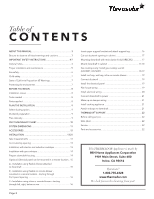
N T S ABOUT THIS MANUAL 3 Be sure to observe all listed warnings and cautions 3 IMPORTANT SAFETY INSTRUCTIONS 4-7 General notes 4 Proper to downdraft 21 THERMADOR® SUPPORT 22 Before calling service 22 Data label 22 Service 22 Parts and accessories 22 This THERMADOR Appliance is made - Thermador UCVM36XS | Installation Instructions - Page 3
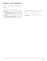
ABOUT THIS MANUAL Be sure to observe all listed warnings and cautions. Look for the triangles with exclamation marks inside. WARNING this advisory. Note: This alerts you to important information and/or tips. Pay special attention to the important safety instructions in the "Safety" section. Page 3 - Thermador UCVM36XS | Installation Instructions - Page 4
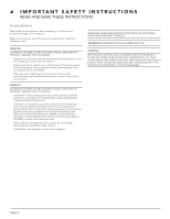
the manufacturer. • Before servicing or cleaning unit, switch power off at service panel and lock the service disconnecting means to prevent power new appliance has been designed to be safe and reliable. Read all instructions carefully before use. These precautions will reduce the risk of burns, - Thermador UCVM36XS | Installation Instructions - Page 5
grounded outlet. Refer to Installation Instructions for details. This appliance is of Limited Product Warranty in the Use and Care Guide. If you have any questions, contact the manufacturer recommended in this manual. Refer all servicing to a factory authorized service center. WARNING Make - Thermador UCVM36XS | Installation Instructions - Page 6
READ AND SAVE THESE INSTRUCTIONS Fire safety WARNING Use this appliance only for its intended use as described in this manual. Always have a working smoke detector near the kitchen. In the event that personal clothing or hair catches ire, drop and roll immediately to extinguish lames. - Thermador UCVM36XS | Installation Instructions - Page 7
safety When children become old enough to use the appliance, it is the responsibility of the parents or legal guardians to ensure that they are instructed in safe practices by qualiied persons. Do not allow anyone to climb, stand, lean, sit, or hang on any part of an appliance. This can - Thermador UCVM36XS | Installation Instructions - Page 8
see page 13) 2 - Support legs Tools needed • Measuring instructions 2 - Upper Support Brackets UGSEUEGTIAUDDÍNEA'EDDDN'CUETATRUIRLESEITOSIGAEYUTNCIIDOUEINDADO MAVSEVTNEETNRITLPIALITEAECDUEOR®RSSDEEERNICTEIASRSODTORDWÉESSNCDSERÉNRADFIEETNMVTAEESNTSTEIELRRAPITEIOEMRCAEMSDTERPIECE® Use and Care guide - Thermador UCVM36XS | Installation Instructions - Page 9
applications, the unit cannot be used in conjunction with a recirculation unit. THERMADOR® recommends not exceeding 50 ft. (15 m) of equivalent duct. Plan frame (not provided) on the base of the cabinet loor. (See lex blower instructions.) Cabinet depths of 24" (610 mm) to 30" (762 mm) are required - Thermador UCVM36XS | Installation Instructions - Page 10
(7.6) 2 (0.6) 2 (0.6) 2 (0.6) 2 (0.6) 2 (0.6) 2 (0.6) 20 (6.1) 3¼" x 10" (83 mm x 254 mm), Roof jack and shutter N/A 2 (0.6) NOTE: These commonly used installation parts can be purchased at a local hardware store. THERMADOR® does not manufacture these parts. Measurements in inches (mm). Page 10 - Thermador UCVM36XS | Installation Instructions - Page 11
RD. DUCT PLATE CVTFRONT10 10" (254 mm) RD. DUCT PLATE UCVM30XS UCVM36XS UCVP36XS DOWNDRAFT FRONT REAR DUCTING 29.750 in 756 mm (Chimney DOWN) 41 750 in 1060 mm (Chimney UP) 2.410 in 61 mm *Not available from Thermador. Purchase locally. SIDE DUCTING 7.500 in 191 mm 5.750 in 146 mm CVTSIDE10 - Thermador UCVM36XS | Installation Instructions - Page 12
A C C E S S O R I E S (purchase separately) Flexible Blower Thermador Model VTD600P Inline and Remote Blowers Thermador Models VTI610, VTR630, VTI1010, VTR1030, VTR1330 MODEL UCVRECIRC UCVFILTER (replacement ilter) CVTFRONT8 CVTFRONT6 CVTFRONT10 EXTNCE5 UCV30ST UCV36ST DESCRIPTION Non-Duct - Thermador UCVM36XS | Installation Instructions - Page 13
I N S TA L L AT I O N Take measurements 1. Refer to the cooktop installation instructions for dimensions of cooktop, countertop cut-out, and cabinet requirements. However, it is recommended that oversized cabinets be used for easier installation. Custom island designs - Thermador UCVM36XS | Installation Instructions - Page 14
Prepare downdraft housing 1. Place the downdraft on its back on a table or lat work surface. UPPER SUPPORT BRACKETS DISCHARGE COVERS SUPPORT LEG NUT (KEEP) SCREWS (DISCARD) NUTS (KEEP) 2. Detach the upper support brackets from the downdraft by cutting off the tie wraps. Remove and set aside both - Thermador UCVM36XS | Installation Instructions - Page 15
32 hex nuts and electrical panel. 4. Place blower over studs around front panel opening. 5. Tighten hex nuts to secure blower in place. (4) BOLTS BLOWER SUPPORT LEGS Based on blower and ducting option selected, go to the relevent section: A - Installation using flexible blower attached to downdraft - Thermador UCVM36XS | Installation Instructions - Page 16
x 19" (48 mm x 483 mm) to 6", 8", or 10" (152 mm, 203 mm, or 254 mm) round transition to housing when installing ductwork. Insert upper support brackets and attach support legs 1. Slide upper suport brackets into slide channel at top left and right of unit. Page 16 2. Attach previously removed - Thermador UCVM36XS | Installation Instructions - Page 17
installed using a recirculation kit, please follow the installation instructions for the recirculation kit (UCVRECIRC) prior to installing and opening as far back as possible and make sure it is level. 2. Extend support legs and attach to bottom of cabinet with (2) screws through each leg. Tighten - Thermador UCVM36XS | Installation Instructions - Page 18
base. Kit includes trim seal, toe-kick cover grille, and cabinet hole cover grille. 2 No. 10 x 0.500 WOOD SCREW 3. Extend upper support brackets and attach to sides of cabinet with (2) screws through each bracket. Installations using lexible blower only: (4) BOLTS 1 FLEXIBLE BLOWER 4. Extend - Thermador UCVM36XS | Installation Instructions - Page 19
No.0-M91, UL 507. Have a qualiied electrical technician check the grounding of the appliance. Do not ground to a gas line. Keep these installation instructions for future reference. Ensure that the wire diameter meets the requirements of the latest version of all applicable standards and laws in the - Thermador UCVM36XS | Installation Instructions - Page 20
Cable Connection Kit (EXTNSET4) can be used in place of the ROMEX or conduit wiring. Please follow all required and recommended wiring instructions in this manual and the extension cable kits. 5. Connect power wires to wires in electrical panel wiring box as shown. Cap off Low (Speed 1) wire - Thermador UCVM36XS | Installation Instructions - Page 21
and remove the front panel to access the ilter area. Make-up air damper wiring (if required) (Refer to make-up air damper instructions.) MAKE-UP AIR DAMPER CONTACTS Connects to 2 contacts on electrical panel. ENDCAP RETAINING SCREW Install cooking appliance Align the cooking appliance with - Thermador UCVM36XS | Installation Instructions - Page 22
THERMADOR® SUPPORT Before calling service See the Use and Care Manual for troubleshooting information. Refer to the "Statement of Limited Product Warranty". To reach a service representative, see the contact information at the front of the manual. Please be prepared with the information printed on - Thermador UCVM36XS | Installation Instructions - Page 23
gauche, à droite, en dessous ou à l'arrière 37 Insertion des supports de ixation supérieurs et installation des pieds 37 Découpage de l'ouverture pour THERMADOR 43 Avant d'appeler le service à la clientèle 43 Étiquette signalétique 43 Service 43 Pièces et accessoires 43 Cet appareil THERMADOR - Thermador UCVM36XS | Installation Instructions - Page 24
À PROPOS DE CE MANUEL Assurez-vous de respecter tous les avertissements et mises en garde énumérés. Cherchez les triangles avec des points d'exclamation à l'intérieur. AVERTISSEMENT Ceci indique que le non-respect de cet avertissement peut causer des blessures graves ou la mort. ATTENTION Ceci - Thermador UCVM36XS | Installation Instructions - Page 25
INSPECTEUR LOCAL. AVERTISSEMENT Lorsqu'il est bien entretenu, votre nouvel appareil est conçu pour être sécuritaire et iable. Lisez attentivement ces instructions avant d'utiliser l'appareil. Ces précautions réduiront les risques de brûlures, de chocs électriques, d'incendie et de blessures. Lorsque - Thermador UCVM36XS | Installation Instructions - Page 26
le uniquement à une prise correctement mise à la terre. Consultez les instructions d'installation pour obtenir plus de détails. Cet appareil est pré rieur. Consultez la déclaration de Garantie Limitée du produit dans le Guide d'utilisation et d'entretien. Si vous avez des questions, communiquez avec - Thermador UCVM36XS | Installation Instructions - Page 27
CONSIGNES DE SÉCURITÉ IMPORTANTES LISEZ CES DIRECTIVES ET CONSERVEZ-LES Sécurité incendie AVERTISSEMENT Utilisez cet appareil uniquement aux ins auxquelles il a été conçu, tel qu'il est indiqué dans ce manuel. Ayez toujours un détecteur de fumée fonctionnel près de la cuisine. Si vos vêtements ou - Thermador UCVM36XS | Installation Instructions - Page 28
CONSIGNES DE SÉCURITÉ IMPORTANTES LISEZ CES DIRECTIVES ET CONSERVEZ-LES Sécurité de l'enfant Lorsque des enfants sont en âge d'utiliser l'appareil, il incombe aux parents ou aux tuteurs légaux de veiller à ce que des personnes qualiiées leur enseignent les pratiques sécuritaires. Ne laissez - Thermador UCVM36XS | Installation Instructions - Page 29
® Directives d'installation 2 - Supports de ixation supérieurs UGSEUEGTIAUDDÍNEA'EDDDN'CUETATRUIRLESEITOSIGAEYUTNCIIDOUEINDADO MAVSEVTNEETNRITLPIALITEAECDUEOR®RSSDEEERNITCEIASRSODTODRWEÉSSNCDSERÉNRADFIEETNMVTAEESNTSTEIELRRAPITEIOEMRCAESMDTERPIECE® Guide d'utilisation et d'entretien Diagramme - Thermador UCVM36XS | Installation Instructions - Page 30
avec un ensemble de recirculation si l'appareil de cuisson est au gaz. THERMADOR® recommande de ne pas dépasser 50 pi (15 mètres) de conduit ou un cadre (non fourni) appuyé sur la base de l'armoire. (Consulter les instructions du ventilateur Flex). Une armoire de 24 po à 30 po (610 mm à 762 - Thermador UCVM36XS | Installation Instructions - Page 31
10 (254) 6 (152) 8 (203) 10 (254) 2 (0,6) 2 (0,6) 2 (0,6) 2 (0,6) 2 (0,6) 2 (0,6) S.O. 20 (6,1) S.O. 2 (0,6) REMARQUE : Ces pièces d'installation couramment utilisées sont en vente dans les quincailleries locales.THERMADOR® ne fabrique pas ces pièces. Mesures en pouces (millimètres). Page 31 - Thermador UCVM36XS | Installation Instructions - Page 32
PLAQUE DE CONDUIT ROND 10 PO (254 mm) HOTTE À TIRAGE DESCENDANT UCVM30XS UCVM36XS UCVP36XS CONDUITS ARRIÈRE AVANT 29,750 po 756 mm (cheminée VERS LE VERS LE HAUT) 2,410 po 61 mm *Non disponible auprès de Thermador Acheter localement. Page 32 AVANT UCVRECIRC ENSEMBLE DE RECIRCULATION 16,000 po - Thermador UCVM36XS | Installation Instructions - Page 33
C C E S S O I R E S (vendus séparément) Ventilateur flexible Ventilateurs en ligne et à distance Modèle Thermador VTD600P Thermador Modèlels VTI610, VTR630, VTI1010, VTR1030, VTR1330 MODÈLE UCVRECIRC UCVFILTER (Filtre de rechanger) CVTFRONT8 CVTFRONT6 CVTFRONT10 EXTNCE5 UCV30ST UCV36ST DESCRIPTION - Thermador UCVM36XS | Installation Instructions - Page 34
I N S TA L L AT I O N Prise de mesures 1. Consulter les directives d'installation de la surface de cuisson pour les dimensions de la surface de cuisson, de l'ouverture à découper dans le comptoir et de l'armoire. Toutefois, il est recommandé que l'armoire soit plus grande que nécessaire pour - Thermador UCVM36XS | Installation Instructions - Page 35
la hotte encastrée sur le dos sur une table ou une surface de travail plane. SUPPORTS DE FIXATION SUPÉRIEURS COUVERCLES D'ÉJECTION PIED ÉCROU (GARDER) VIS (JETER) ÉCROUS (GARDER) 2. Retirer les supports de ixation supérieurs de la hotte en coupant les attaches autobloquantes. Enlever et mettre - Thermador UCVM36XS | Installation Instructions - Page 36
du panneau avant. 5. Serrer les écrous hexagonaux pour ixer le ventilateur en place. (4) BOULONS PIEDS DE SUPPORT DU VENTILATEUR 6. Retirer les boulons du boîtier du ventilateur Flex. Fixer les pieds de support du ventilateur sur le boîtier du ventilateur Flex au moyen des ces (4) boulons. Ne pas - Thermador UCVM36XS | Installation Instructions - Page 37
) à 6 po (152 mm), 8 po (203 mm) ou 10 po (254 mm) rond lors de la pose du conduit. Insertion des supports de fixation supérieurs et installation des pieds 1. Glisser les supports de ixation supérieurs dans les glissières latérales de la hotte. 2. Fixer les pieds retirés précédemment à la - Thermador UCVM36XS | Installation Instructions - Page 38
I N S TA L L AT I O N Découpage de l'ouverture pour conduits dans l'armoire 1. Mesurer et marquer l'endroit où découper l'ouverture pour les conduits dans l'armoire, selon l'option sélectionnée. Utiliser les dimensions indiquées dans l'illustration ci-dessous pour planiier l'accès des conduits - Thermador UCVM36XS | Installation Instructions - Page 39
supérieurs et les ixer sur les côtés de l'armoire avec (2) vis dans chaque support. Installations avec ventilateur lexible seulement : (4) BOULONS VENTILATEUR FLEXIBLE 1 B B C C A B B A B 4. Allonger les pieds et les ixer au bas de l'armoire avec une vis dans chaque pied. Serrer - Thermador UCVM36XS | Installation Instructions - Page 40
à un électricien qualiié de vériier la mise à la terre de l'appareil. N'effectuez pas une mise à la terre vers un conduit de gaz. Conserver ces instructions d'installation pour référence ultérieure. S'assurer que le diamètre de câble respecte les exigences de la dernière version de toutes les normes - Thermador UCVM36XS | Installation Instructions - Page 41
I N S TA L L AT I O N Installation du câblage électrique B - Câblage de ventilateur à distance ATTENTION : La pose de l'appareil et les travaux d'électricité doivent être effectués par des personnes qualiiées en respectant la réglementation en vigueur, notamment les codes et les normes de la - Thermador UCVM36XS | Installation Instructions - Page 42
Câblage du dispositif d'apport d'air (si requis) (Consulter les instructions pour le dispositif d'apport d'air) BORNES POUR DISPOSITIF D'APPORT D'AIR vis de retenue du capot d'extrémité. 2. Placer le capot par dessus le support. 3. Utiliser la clé spéciale incluse pour visser complètement la vis de - Thermador UCVM36XS | Installation Instructions - Page 43
sitez pas à contact notre STAR® Service à la clientèle si vous avez des questions, ou dans l'éventualité improbable où votre appareil THERMADOR® nécessiterait une réparation. Notre équipe de réparation est prête à vous aider. États-Unis 800 735-4328 www.thermador.com/support Canada 800 735-4328 www - Thermador UCVM36XS | Installation Instructions - Page 44
CONTENIDO ACERCA DE ESTE MANUAL 45 Asegúrese de observar todas las advertencias y precauciones de la lista 45 63 Fije las tapas de extremo en el tiro descendente 63 APOYO DE THERMADOR 64 Antes de llamar al servicio 64 Etiqueta de datos 64 Servicio 64 Piezas y accesorios 64 Este electrodom - Thermador UCVM36XS | Installation Instructions - Page 45
ACERCA DE ESTE MANUAL Asegúrese de observar todas las advertencias y precauciones de la lista. Busque los triángulos con signos de admiración dentro. ADVERTENCIA Esto indica que podría - Thermador UCVM36XS | Installation Instructions - Page 46
INSTRUCCIONES IMPORTANTES DE SEGURIDAD LEA Y CONSERVE ESTAS INSTRUCCIONES Notas generales Nota: Examine el electrodoméstico antes de desempacarlo. En caso de daños durante el transporte, no lo conecte. Nota: No retire nada de la cinta de aluminio, ya que se necesita para sellar las fugas de aire. - Thermador UCVM36XS | Installation Instructions - Page 47
con un proveedor de servicio autorizado. No repare ni reemplace ninguna pieza del electrodoméstico a menos que así se recomiende especíicamente en este manual. Reiera todo el servicio a un centro de servicio autorizado de fábrica. ADVERTENCIA Asegúrese de que el electrodoméstico y las luces estén fr - Thermador UCVM36XS | Installation Instructions - Page 48
Y CONSERVE ESTAS INSTRUCCIONES Seguridad ante incendios ADVERTENCIA Use este electrodoméstico únicamente para lo que está diseñado, tal como se describe en este manual. Siempre tenga cerca de la cocina un detector de humos en funcionamiento. En caso de que la ropa o el cabello se incendie, déjese - Thermador UCVM36XS | Installation Instructions - Page 49
INSTRUCCIONES IMPORTANTES DE SEGURIDAD LEA Y CONSERVE ESTAS INSTRUCCIONES Seguridad con los niños Cuando los niños crecen lo suiciente como para usar el electrodoméstico, es responsabilidad de los padres o tutores legales asegurarse de que personas caliicadas los instruyan en prácticas seguras. No - Thermador UCVM36XS | Installation Instructions - Page 50
ANTES DE COMENZAR Revisión de la instalación Este sistema de corriente descendente se puede usar para extraer los subproductos de la cocción como el calor, el vapor y el humo que pueden crearse al cocinar con estufas de gas o eléctricas. Gracias a su diseño versátil, hay seis (6) opciones básicas - Thermador UCVM36XS | Installation Instructions - Page 51
de la casa, hacia la cochera o hacia algún espacio cerrado). La unidad no se puede usar en conjunto con una unidad de recirculación. THERMADOR® recomienda que no se superen los 50 pies (15 m) de conducto equivalente. Planee los gabinetes Para extracción a la izquierda, a la derecha o a la parte - Thermador UCVM36XS | Installation Instructions - Page 52
10 (254) 6 (152) 8 (203) 10 (254) N/A N/A 25 (7.6) 2 (0.6) 2 (0.6) 2 (0.6) 2 (0.6) 2 (0.6) 2 (0.6) 20 (6.1) 2 (0.6) NOTA: Estas piezas de instalación utilizadas usualmente se pueden comprar en una ferretería local. THERMADOR® no fabrica estas piezas. Mediciones en pulgadas (milímetros). Página 52 - Thermador UCVM36XS | Installation Instructions - Page 53
pulg. 405 mm 7.976 pulg.357 mm 203 mm TIRO DESCENDENTE SALIDA UCVM30XS UCVM36XS UCVP36XS CVTFRONT6 PLACA DE CONDUCTO RED. DE 6 PULG. (152 mm) CVTFRONT8 (Chimenea HACIA ARRIBA) 2.410 pulg. 61 mm *No está disponible con Thermador Compre a nivel local. FRENTE 16.000 pulg. 406 mm 3.750 pulg - Thermador UCVM36XS | Installation Instructions - Page 54
A C C E S O R I O S (se compran por separado) Ventilador flexible Ventiladores en línea y remotos Thermador Modelo VTD600P Thermador Modelos VTI610, VTR630, VTI1010, VTR1030, VTR1330 MODELO UCVRECIRC UCVFILTER (iltro de reemplazo) CVTFRONT8 CVTFRONT6 CVTFRONT10 EXTNCE5 UCV30ST UCV36ST CVDUCT2 - Thermador UCVM36XS | Installation Instructions - Page 55
I N S TA L A C I Ó N Tome medidas 1. Consulte las instrucciones de instalación de la estufa para ver las dimensiones de la estufa, el recorte en la cubierta y los requerimientos del gabinete. Sin embargo, se recomienda usar gabinetes de mayor tamaño para facilitar la instalación. Los diseños de - Thermador UCVM36XS | Installation Instructions - Page 56
I N S TA L A C I Ó N Instalación con estufas a gas La dimensión "BT" es el espesor del protector contra salpicaduras. Deje 1/2 pulg (13 mm de separación entre el recorte de la ventilación y el protector contra salpicaduras. Ancho de recorte de tiro descendente: Plantilla 2-1/8 pulg. (54 mm) 30 - Thermador UCVM36XS | Installation Instructions - Page 57
I N S TA L A C I Ó N Opcional: El panel eléctrico se puede montar A - Instalación usando un ventilador flexible en un sitio remoto fijo al tiro descendente Por ejemplo: La parte inferior del gabinete tiene un cajón, frente al tiro descendente. Esto puede requerir que el panel eléctrico se monte en - Thermador UCVM36XS | Installation Instructions - Page 58
I N S TA L A C I Ó N B - Instalación usando un ventilador flexible o remoto - con conductos a través de la abertura del panel frontal PRECAUCIÓN Si el ventilador lexible está montado en línea: No utilice las patas por sí solas como apoyo. Tal vez sea necesario añadir apoyo extra para el ventilador - Thermador UCVM36XS | Installation Instructions - Page 59
I N S TA L A C I Ó N Recorte la abertura para el conducto en el gabinete 1. Mida y marque dónde va a cortar la abertura para el conducto en el gabinete, con base en la opción de conducto seleccionada. Utilice las dimensiones de la siguiente ilustración para ayudarle a planear cómo y dónde - Thermador UCVM36XS | Installation Instructions - Page 60
I N S TA L A C I Ó N Solo estufas de gas: Instale el juego para sellar estufas de gas (UCV30ST, UCV36ST) (se compra por separado) Disponible para aplicarse con estufas de gas, donde se requiere el sellado adecuado y se requieren oriicios en la base del gabinete. El juego incluye el sello de la - Thermador UCVM36XS | Installation Instructions - Page 61
I N S TA L A C I Ó N Planee el cableado de la casa E B E A G CD D F D Limpie la supricie de la cubierta (B) con alcohol isopropílico o alcohol de frotamiento. Retire las TIRAS DE CINTAS para relevar el lado con adhesivo de la cinta del lado posterior del SOPORTE DE LA MOLDURA (A). E Centre el - Thermador UCVM36XS | Installation Instructions - Page 62
ón del cable de extensión (EXTNSET4) en lugar del cable ROMEX o del cableado de conductos. Siga todas las instrucciones de cableado necesarias y recomendadas en este manual y en los kits de cable de extensión. 5. Conecte los cables eléctricos con los cables de la caja de cableado del panel eléctrico - Thermador UCVM36XS | Installation Instructions - Page 63
I N S TA L A C I Ó N Conecte el tiro descendente a la electricidad Fije las tapas de extremo en el tiro descendente LLAVE ESPECIAL (INCLUIDA) 1. Enchufe el cable del panel eléctrico en el receptáculo inferior, como se muestra. Conecte el cable eléctrico del tiro descendente al receptáculo de tres - Thermador UCVM36XS | Installation Instructions - Page 64
® necesitara servicio. Nuestro equipo de servicio está listo para ayudarle. EE.UU. 800-735-4328 www.thermador.com/support Canadá 800-735-4328 www.thermador.ca Piezas y accesorios Las piezas, iltros, desincrustantes, limpiadores de acero inoxidable y más se pueden comprar en la tienda electrónica
-
 1
1 -
 2
2 -
 3
3 -
 4
4 -
 5
5 -
 6
6 -
 7
7 -
8
-
9
-
10
-
11
-
12
-
13
-
14
-
15
-
16
-
17
-
18
-
19
-
20
-
21
-
22
-
23
-
24
-
25
-
26
-
27
-
28
-
29
-
30
-
31
-
32
-
33
-
34
-
35
-
36
-
37
-
38
-
39
-
40
-
41
-
42
-
43
-
44
-
45
-
46
-
47
-
48
-
49
-
50
-
51
-
52
-
53
-
54
-
55
-
56
-
57
-
58
-
59
-
60
-
61
-
62
-
63
-
64
 |
 |

Masterpiece
®
Series Downdraft Hood
Installation
GUIDE
UCVM30XS, UCVM36XS, UCVP36XS
THERMADOR.COM