Tanaka TBC-255SFK Owner's Manual - Page 9
Brush Cutter
 |
View all Tanaka TBC-255SFK manuals
Add to My Manuals
Save this manual to your list of manuals |
Page 9 highlights
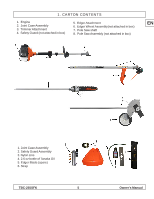
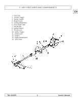
5. UNIT ASSEMBLY & OPERATION Power Head Assembly Brush Cutter EN The TBC-255SFK utilizes one engine to power all of the various attachments. The top portion of the shaft (closest to the engine) is common to all of the attachments. The brushcutter shaft (lower portion), requires set-up as follows: 1 1. Remove all of the product contents from the carton. Identify the engine with the shaft and handle attached as shown : 2. Locate the lower section of brushcutter shaft as shown: 3. Before the lower shaft assembly can be joined to the upper shaft, it is necessary to install the coupler onto the upper shaft. Carefully place all three washers over the end of the shaft protruding fro m the shaft assembly on the engine side as depicted: With all the washers in place over the end of the shaft, place the connector over the shaft end with the washers so the locator bolt (1) on the connector is aligned with the locator hole on the shaft. After the locator bolt is secured, tighten the connector to the shaft using the pinch bolt (2). With the connector assembled to the upper shaft, you can now attach the lower shaft assembly as described in the next section. 4. The lower bruschutter section comes with the No-Brainer cutting head attached. Place the opposite end of the shaft into the coupler on the upper shaft as depicted: 5. Make sure the shaft is fully inserted and that the locking bolt is properly aligned with the location hole and that the tightening knob is securely tightened. Failure to properly connect the shaft sections will result in damage to the shaft and possible injury to the operator. 6. Install the safety guard onto the shaft as shown. Use caution when handling the safety guard as the shield uses a sharp line limiter blade. CAUTION Your TBC-255SFK is categorized under the ANSI safety standard B175.3, as a "convertible grass trimmer". This means that while your machine does not come equipped as blade capable, it is possible to convert it for use with a steel blade (commonly referred to as a "brushcutter"). By purchasing the blade kit (Tanaka part number 748503), you will have the necessary components to safely use a blade. These components include a blade capable debris shield, barrier bar, safety strap and blade retaining hardware. NEVER ATTEMPT TO USE THIS MACHINE WITH A STEEL BLADE WITHOUT FIRST PROPERLY CONVERTING THE UNIT TO A BLADE CAPABLE BRUSHCUTTER! TBC-255SFK 9 Owner's Manual
-
 1
1 -
2
-
3
-
 4
4 -
 5
5 -
 6
6 -
 7
7 -
 8
8 -
 9
9 -
 10
10 -
 11
11 -
 12
12 -
 13
13 -
 14
14 -
15
-
16
-
17
-
18
-
19
-
20
-
21
-
22
 |
 |
