Tanaka TBC-255SFK Owner's Manual - Page 12
Edger Attachment
 |
View all Tanaka TBC-255SFK manuals
Add to My Manuals
Save this manual to your list of manuals |
Page 12 highlights
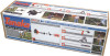
Edger Assembly 5. UNIT ASSEMBLY & OPERATION Edger Attachment The edger attachment comes assembled with the exception of attaching the wheel to the blade guard assembly. Using the carriage bolt included with the wheel, attach to the blade guard bracket as shown. EN Edger Operating Procedures By loosening the safety guard assembly bolts (shown as reference number 3), the angle of the guard can be adjusted for preference. Be sure that the guard does not come off of the gear case lip on which it is intended to ride. Attempting to tighten it in place when incorrectly positioned can cause damage. Before proceeding with this section, BE SURE YOU HAVE READ AND UNDERSTAND THE GENERAL WARNINGS AND SAFETY INSTRUCTIONS DESCRIBED IN SECTION 3. Use only for edging the type of grass and other growth for which the machine is designed. 1. Adjust the wheel within the guard bracket as depicted: Adjust cutting depth by loosening knob nut (1) and moving location of wheel up or down. To increase cutting depth, move wheel location upwards and to decrease , move it lower. After the location is decided, tighten knob nut (1) securely. NOTE! All adjustments should be made after engine has stopped completely, stop switch is in the OFF position and cutting attachment has stopped turning. 2. Always hold unit firmly with both hands and keep body well balanced. 3. Always operate the edger positioned with the engine on the right side of the operator. WARNING! Operate the unit from a position where guard blocks the line of sight to the cutting blade. WARNING! If blade should strike against stones or other debris, stop the engine and visually inspect the blade, guard and related parts for any damage. TBC-255SFK 12 Owner's Manual
-
 1
1 -
2
-
3
-
4
-
5
-
6
-
 7
7 -
 8
8 -
 9
9 -
 10
10 -
 11
11 -
 12
12 -
 13
13 -
 14
14 -
 15
15 -
 16
16 -
 17
17 -
18
-
19
-
20
-
21
-
22
 |
 |
