Stihl MS 462 C-M Instruction Manual - Page 44
Mixing Fuel and Refueling the Chain Saw
 |
View all Stihl MS 462 C-M manuals
Add to My Manuals
Save this manual to your list of manuals |
Page 44 highlights
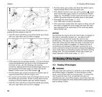
English Closing To close the tank: 1 4 1 13 Mixing Fuel and Refueling the Chain Saw A B C 1 1 1 0000-GXX-2935-A1 0000-GXX-2134-A1 2 2 2 2 3 ► Raise the grip on the top of the cap until it is upright at a 90° angle. Insert the cap in the fuel tank opening with the exterior positioning mark (1) lined up with the "unlocked" symbol (2) on the fuel tank housing. ► Using the grip, press the cap down firmly while turning it clockwise to the closed position (approximately 1/4 turn). In the closed position, the interior (4) and exterior (1) positioning marks will align with the "locked" symbol (3) on the fuel tank housing. ► Fold the grip flush with the top of the cap and check for tightness. ► If the grip does not lie completely flush with the cap or the detent on the grip does not fit in the corresponding recess in the tank opening, or if the cap is loose, the cap is not properly seated and you must repeat the above steps. ► Also refer to the procedure below for returning the base of the cap to the proper starting position for installation. If the filler cap will not engage into the tank housing The base of the filler cap is rotated in relation to the upper part. If the cap does not drop fully into the fuel tank opening when the positioning marks (1, 2) line up, or if it does not tighten properly when turned, the base of the cap may be prematurely rotated in relation to the top. Such misalignment can result from handling, cleaning or an improper attempt at tightening. - Illustrations A and B: The base of the cap is prematurely rotated to the closed position and is not in the correct starting position for installation. The tank will not seal in this configuration. Note: in Illustrations A and B, the interior positioning marks (1) are in line with the exterior positioning marks (2). - Illustration C: The bottom of the cap is in the correct starting position for installation. Note: in Illustration C, the interior positioning mark (1) is under the grip and not in line with the outer positioning mark (2). To return the base of the cap to the proper starting position for installation: A B C 1 0000-GXX-3136-A1 2 42 0458-790-8621-A
-
 1
1 -
2
-
3
-
4
-
5
-
6
-
7
-
8
-
9
-
10
-
11
-
12
-
13
-
14
-
15
-
16
-
17
-
18
-
19
-
20
-
21
-
22
-
23
-
24
-
25
-
26
-
27
-
28
-
29
-
30
-
31
-
32
-
33
-
34
-
35
-
36
-
37
-
38
-
 39
39 -
 40
40 -
 41
41 -
 42
42 -
 43
43 -
 44
44 -
 45
45 -
 46
46 -
 47
47 -
 48
48 -
 49
49 -
50
-
51
-
52
-
53
-
54
-
55
-
56
-
57
-
58
-
59
-
60
-
61
-
62
-
63
-
64
-
65
-
66
-
67
-
68
-
69
-
70
-
71
-
72
-
73
-
74
-
75
-
76
-
77
-
78
-
79
-
80
-
81
-
82
-
83
-
84
-
85
-
86
-
87
-
88
-
89
-
90
-
91
-
92
-
93
-
94
-
95
-
96
-
97
-
98
-
99
-
100
-
101
-
102
-
103
-
104
-
105
-
106
-
107
-
108
-
109
-
110
-
111
-
112
-
113
-
114
-
115
-
116
-
117
-
118
-
119
-
120
-
121
-
122
-
123
-
124
-
125
-
126
-
127
-
128
-
129
-
130
-
131
-
132
-
133
-
134
-
135
-
136
-
137
-
138
-
139
-
140
-
141
-
142
-
143
-
144
-
145
-
146
-
147
-
148
 |
 |
