Stihl MS 261-MS 261 C Instruction Manual - Page 36
Assembling the Chain Saw, 10.1 Cutting Attachment
 |
View all Stihl MS 261-MS 261 C manuals
Add to My Manuals
Save this manual to your list of manuals |
Page 36 highlights
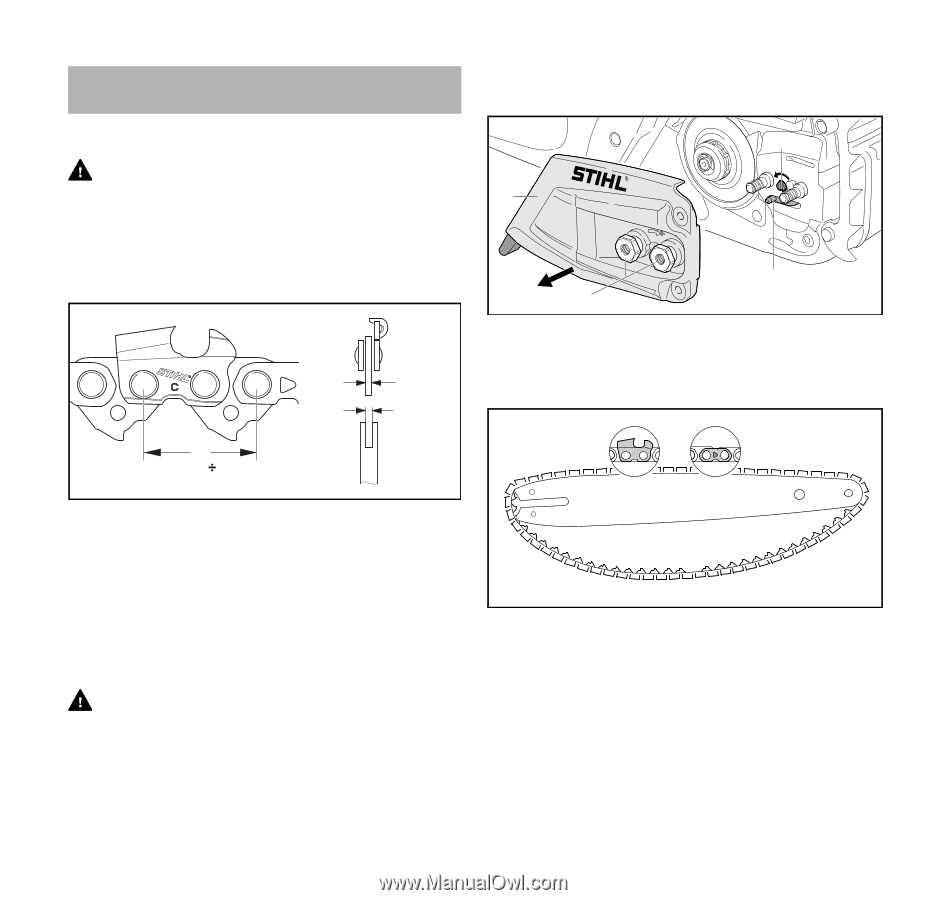
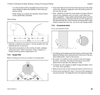
English 10 Assembling the Chain Saw 10 Assembling the Chain Saw To mount the guide bar and chain: ► Shut off the engine, @ 15.1. 0000-GXX-2734-A0 10.1 Cutting Attachment WARNING If non-matching components are used, the cutting attachment will be damaged beyond repair after a short period of operation, and the chain could de-rail, resulting in serious or fatal personal injury. A cutting attachment consists of the chain, guide bar and chain sprocket. 1 2 3 2 4 1 ► Unscrew the nuts (1). ► Remove the chain sprocket cover (2). ► Turn the side chain tensioner (3) counter-clockwise until the tensioning gear (4) sits flush against the housing. 0000-GXX-1445-A0 a 3 t=a 2 0000-GXX-2130-A0 - The pitch (t) of the chain (1), chain sprocket and, if using a Rollomatic guide bar, the nose sprocket must match. - The drive link gauge (2) of the chain must match the groove width of the guide bar (3). 10.2 Mounting and Removing the Guide Bar and Chain 10.2.1 Mounting the Guide Bar and Chain WARNING The chain has many sharp cutters. If they contact your flesh, they will cut you, even if the chain is not moving, @ 5.4. Always wear heavy-duty work gloves when mounting or otherwise handling the chain, @ 5.3. ► Position the chain in the groove of the guide bar, starting at the tip. ► Make sure that the cutters in the groove on the top side of the guide bar face the tip of the bar. STIHL chains are manufactured with arrows on the tie straps to help the operator determine the proper direction of the chain. Arrows on the tie straps on the top of the bar must point toward the bar tip. 34 0458-573-8621-D
-
 1
1 -
2
-
3
-
4
-
5
-
6
-
7
-
8
-
9
-
10
-
11
-
12
-
13
-
14
-
15
-
16
-
17
-
18
-
19
-
20
-
21
-
22
-
23
-
24
-
25
-
26
-
27
-
28
-
29
-
30
-
 31
31 -
 32
32 -
 33
33 -
 34
34 -
 35
35 -
 36
36 -
 37
37 -
 38
38 -
 39
39 -
 40
40 -
 41
41 -
42
-
43
-
44
-
45
-
46
-
47
-
48
-
49
-
50
-
51
-
52
-
53
-
54
-
55
-
56
-
57
-
58
-
59
-
60
-
61
-
62
-
63
-
64
-
65
-
66
-
67
-
68
-
69
-
70
-
71
-
72
-
73
-
74
-
75
-
76
-
77
-
78
-
79
-
80
-
81
-
82
-
83
-
84
-
85
-
86
-
87
-
88
-
89
-
90
-
91
-
92
-
93
-
94
-
95
-
96
-
97
-
98
-
99
-
100
-
101
-
102
-
103
-
104
-
105
-
106
-
107
-
108
-
109
-
110
-
111
-
112
-
113
-
114
-
115
-
116
-
117
-
118
-
119
-
120
-
121
-
122
-
123
-
124
-
125
-
126
-
127
-
128
-
129
-
130
-
131
-
132
-
133
-
134
-
135
-
136
-
137
-
138
-
139
-
140
-
141
-
142
-
143
-
144
-
145
-
146
-
147
-
148
 |
 |