Sharp XG-NV5XB Operation Manual - Page 43
Connection Pin Assignments, RS-232C Port Specifications
 |
View all Sharp XG-NV5XB manuals
Add to My Manuals
Save this manual to your list of manuals |
Page 43 highlights
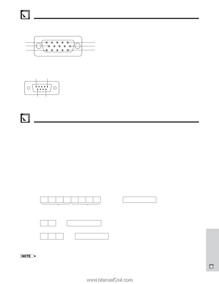
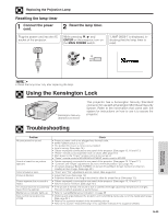
Connection Pin Assignments Analog Computer 1 and 2 Signal Input Ports: 15-pin mini D-sub female connector Computer Input Analog 1. Video input (red) 9. Not connected 2. Video input 10. GND (green/sync on green) 11. GND 5 1 3. Video input (blue) 12. Bi-directional data 10 6 4. Reserve input 1 13. Horizontal sync signal 15 11 5. Composite sync 14. Vertical sync signal 6. Earth (red) 15. Data clock 7. Earth (green/sync on green) 8. Earth (blue) RS-232C Port: 9-pin D-sub male connector 15 Pin No. 1 2 3 4 5 6 Signal CD RD SD ER SG DR Name Receive Data Send Data Signal Ground Data Set Ready I/O Input Output Output Reference Not connected Connected to internal circuit Connected to internal circuit Not connected Connected to internal circuit Not connected 69 7 RS Request to Send Output Connected to internal circuit 8 CS Clear to send Input Connected to internal circuit 9 CI Not connected RS-232C Port Specifications PC control A computer can be used to control the projector by connecting an RS-232C cable (cross type, sold separately) to the projector. (See page 15 for connection.) Communication conditions Set the serial port settings of the computer to match that of the table on the next page. Signal format: Conforms to RS-232C standard. Baud rate: 9,600 bps Data length: 8 bits Parity bit: NON Stop bit: 1 bit Flow control: None Basic format Commands from the computer are sent in the following order: command, parameter, and return code. After the projector processes the command from the computer, it sends a response code to the computer. Command format C1 C2 C3 C4 P1 P2 P3 P4 Return code (0DH) Command 4-digits Response code format Normal response Parameter 4-digits O K Return code (0DH) Problem response (communication error or incorrect command) E R R Return code (0DH) When more than one code is being sent, send each command only after the OK response code for the previous command from the projector is verified. • When using the computer control function of the projector, the projector operating status cannot be read to the computer. Therefore, confirm the status by transmitting the display commands for each adjustment menu and checking the status with the On-screen Display. If the projector receives a command other than a menu display command, it will execute the command without displaying the On-screen Display. E-42 Appendix
-
 1
1 -
2
-
3
-
4
-
5
-
6
-
7
-
8
-
9
-
10
-
11
-
12
-
13
-
14
-
15
-
16
-
17
-
18
-
19
-
20
-
21
-
22
-
23
-
24
-
25
-
26
-
27
-
28
-
29
-
30
-
31
-
32
-
33
-
34
-
35
-
36
-
37
-
 38
38 -
 39
39 -
 40
40 -
 41
41 -
 42
42 -
 43
43 -
 44
44 -
 45
45 -
 46
46 -
 47
47 -
 48
48 -
49
-
50
-
51
-
52
-
53
-
54
 |
 |