SanDisk 8GB ULTRA Product Manual - Page 51
Status & Alternate Status Registers Address-1F7[177]&3F6[376]; Offsets 7 &, Device
 |
UPC - 619659021566
View all SanDisk 8GB ULTRA manuals
Add to My Manuals
Save this manual to your list of manuals |
Page 51 highlights
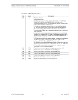
SanDisk CompactFlash Card OEM Product Manual ATA Register Set and Protocol 4.5.9 Status & Alternate Status Registers (Address-1F7[177]&3F6[376]; Offsets 7 & Eh) These registers return the card status when read by the host. Reading the Status Register clears a pending interrupt while reading the Auxiliary Status Register does not. The meaning of the status bits are described as follows: D7 D6 D5 D4 D3 D2 D1 BUSY RDY DWF DSC DRQ CORR 0 D0 ERR Bit Name Description D7 BUSY Set when the CompactFlash Card has access to the command buffer and registers and the host is locked out from accessing the command register and buffer. No other bits in this register are valid when this bit is set to a 1. D6 RDY RDY indicates whether the device is capable of performing card operations. This bit is cleared at power-up and remains cleared until card is ready to accept a command. D5 DWF If set, indicates a write fault has occurred. D4 DSC Set when the card is ready. D3 DRQ Set when the card requires that information be transferred either to or from the host through the Data Register. D2 CORR Set when a correctable data error has been encountered and the data has been corrected. This condition does not terminate a multi-sector read operation. D1 0 Always set to 0. D0 ERR Set when the previous command has ended in some type of error. The bits in the Error Register contain additional information describing the error. 4.5.10 Device Control Register (Address-3F6[376]; Offset Eh) This register is used to control the CompactFlash Memory Card interrupt request and to issue an ATA soft reset to the card. The bits are defined as follows: D7 D6 D5 D4 D3 D2 D1 D0 X X X X 1 SW Rst -IEn 0 © 2007 SanDisk Corporation 4-7 Rev. 12.0, 02/07
-
 1
1 -
2
-
3
-
4
-
5
-
6
-
7
-
8
-
9
-
10
-
11
-
12
-
13
-
14
-
15
-
16
-
17
-
18
-
19
-
20
-
21
-
22
-
23
-
24
-
25
-
26
-
27
-
28
-
29
-
30
-
31
-
32
-
33
-
34
-
35
-
36
-
37
-
38
-
39
-
40
-
41
-
42
-
43
-
44
-
45
-
 46
46 -
 47
47 -
 48
48 -
 49
49 -
 50
50 -
 51
51 -
 52
52 -
 53
53 -
 54
54 -
 55
55 -
 56
56 -
57
-
58
-
59
-
60
-
61
-
62
-
63
-
64
-
65
-
66
-
67
-
68
-
69
-
70
-
71
-
72
-
73
-
74
-
75
-
76
-
77
-
78
-
79
-
80
-
81
-
82
-
83
-
84
-
85
-
86
-
87
-
88
-
89
-
90
-
91
-
92
-
93
-
94
-
95
-
96
-
97
-
98
-
99
-
100
-
101
-
102
-
103
-
104
-
105
-
106
-
107
-
108
 |
 |
