Rane MLM82S MLM82S Manual - Page 5
Front Panel Description - manual
 |
View all Rane MLM82S manuals
Add to My Manuals
Save this manual to your list of manuals |
Page 5 highlights
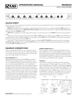
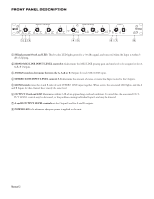
FRONT PANEL DESCRIPTION 1 4 6 2 8 0 10 A+B SIG / OL LEVEL ASSIGN MONO MIC / LINE INPUTS 2 3 4 6 4 6 2 8 2 8 0 10 A+B SIG / OL LEVEL ASSIGN 0 10 A+B SIG /OL LEVEL ASSIGN 4 4 6 2 8 0 10 A+B SIG / OL LEVEL ASSIGN 5 4 6 STEREO LINE INPUTS 6 7 4 6 4 6 8 4 6 2 8 2 8 2 8 2 8 0 10 LEVEL MONO 0 10 LEVEL MONO 0 10 LEVEL MONO 0 10 LEVEL MONO OUTPUTS A B 4 6 4 6 2 82 8 0 10 OL LEVEL 0 10 OL LEVEL 123 45 67 MLM82S MIC / LINE MIXER POWER 8 1 SIGnal present/OverLoad LED. This bi-color LED lights green for a -30 dBu signal, and turns red when the Input is within 3 dB of clipping. 2 MONO MIC/LINE INPUT LEVEL controls 1-4 determine the MIC/LINE preamp gain and mix level to be assigned to the A, A+B, B Outputs. 3 ASSIGN switches determine between the A, A+B or B Outputs for each MIC/LINE input. 4 STEREO LINE INPUT LEVEL controls 5-8 determine the amount of stereo or mono line Input routed to the Outputs. 5 MONO switch mixes the A and B sides of each STEREO LINE input together. When active, the associated LED lights, and the A and B Inputs for that channel have exactly the same level. 6 OUTPUT OverLoad LED illuminates within 3 dB of an approaching overload condition. To avoid this, the associated OUTPUT LEVEL control may be decreased, or the problem-causing individual Input Level may be lowered. 7 A and B OUTPUT LEVEL controls set the Output Level for A and B outputs. 8 POWER LED is lit whenever adequate power is applied to the unit. Manual-2
-
 1
1 -
 2
2 -
 3
3 -
 4
4 -
 5
5 -
 6
6 -
 7
7
 |
 |
