Rane MLM82S MLM82S Manual - Page 4
Mlm82s, Operators Manual
 |
View all Rane MLM82S manuals
Add to My Manuals
Save this manual to your list of manuals |
Page 4 highlights
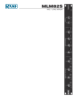
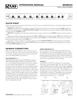
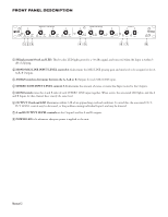
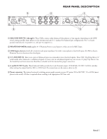
OPERATORS MANUAL MLM82S MIC/LINE MIXER 1 4 6 2 8 0 10 A+B SIG / OL LEVEL ASSIGN MONO MIC / LINE INPUTS 2 3 4 6 4 6 2 8 2 8 0 10 A+B SIG / OL LEVEL ASSIGN 0 10 A+B SIG /OL LEVEL ASSIGN 4 4 6 2 8 0 10 A+B SIG / OL LEVEL ASSIGN 5 4 6 STEREO LINE INPUTS 6 7 4 6 4 6 8 4 6 2 8 2 8 2 8 2 8 0 10 LEVEL MONO 0 10 LEVEL MONO 0 10 LEVEL MONO 0 10 LEVEL MONO OUTPUTS A B 4 6 4 6 2 82 8 0 10 OL LEVEL 0 10 OL LEVEL MLM82S MIC / LINE MIXER POWER QUICK START This section is provided as a convenience for those in a rush. If you are experienced with this unit or other Rane products, these few words will refresh your memory. INPUTS 1 through 4 may be microphone or line level. The choice between the two is made by setting the LINE push buttons on the REAR of the unit next to the MIC/LINE INPUT JACKS. Each microphone input may be assigned to A, B or A+B outputs using the front panel ASSIGN switches. INPUTS 5 through 8 are stereo line inputs which may be set to mono using the recessed MONO switches located on the front panel. Internal switches allow setting output signal levels for MIC or LINE. The factory default setting is LINE. If the MLM82S is connected directly to a power amplifier, equalizer or recorder input, choose LINE level. If the MLM82S is connected to a microphone jack of an existing sound system, choose MIC level. Once Inputs, Outputs, and power are properly connected, with the OUTPUT LEVELS counterclockwise (off ), set the Input LEVELS as high as possible without causing the SIG/OL indicators to blink red except during extreme signal peaks. Now slowly raise the OUTPUT LEVELS as desired. MLM82S CONNECTION When connecting the MLM82S to other components in your system for the first time, leave the power cord for last. This gives you a chance to make mistakes and correct them without damage to your fragile speakers, ears and nerves. MIC/LINE INPUTS 1-4 The four XLR jacks provided on the MLM82S are balanced MIC/LINE inputs. They will also accept unbalanced connectors. Use only shielded cable for inputs. For best noise rejection use two-conductor-plus-shielded wire, even for unbalanced operation. Connect the shield at both ends to help insure proper grounding. See the Sound System Interconnection RaneNote included with this manual for all cable adaptations. Rane follows the AES recommended practice of pin 2 positive, pin 3 negative, and pin 1 to shield. Switch any input connected to a microphone to the MIC position (out) using the associated switches on the rear panel. When connecting line level signals, switch the input to the LINE position (in). A single phantom power switch is provided for the four MIC inputs. If LINE is selected, Phantom Power is disabled for that input. STEREO LINE INPUTS 5-8 The ¼" connectors are line-level balanced/unbalanced Inputs. If the MLM82S is to be used with unbalanced sources, consult the Sound System Interconnection RaneNote included with this manual for proper wiring. Stereo Inputs use both A and B jacks at each INPUT. INPUTS 5 through 8 also serve as mono Inputs when the front panel MONO switch is engaged. OUTPUTS The MLM82S's OUTPUTS are balanced. The same wiring conventions as the XLR Inputs apply. The type of device following the MLM82S must be considered when setting the internal Output Level switch. Choose between LINE (0 dB) or MIC (-40 dB) output, the factory setting is LINE. If the MLM82S is connected directly to a power amplifier input, choose LINE level. If the MLM82S is connected to a microphone jack on an existing sound system, choose MIC level. For unbalanced OUTPUT connections do not tie pin 3 (i.e. "-") to ground. WEAR PARTS: This product contains no wear parts. Manual-1
-
 1
1 -
 2
2 -
 3
3 -
 4
4 -
 5
5 -
 6
6 -
 7
7
 |
 |
