Rane ME60S Instruction Manual - Page 6
Rear Panel Description, Important Note
 |
View all Rane ME60S manuals
Add to My Manuals
Save this manual to your list of manuals |
Page 6 highlights
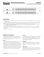
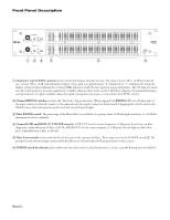
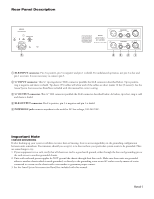
Rear Panel Description ME60S RANE CORPORATION COMMERCIAL AUDIO EQUIPMENT 24TJ R 100-240 V 50/60 Hz 12 WATTS 5 WIRING Tip / Pin 2 = Positive (+) Ring / Pin 3 = Negative (-) Sleeve = Signal Ground Pin 1 = Chassis Ground All audio jacks are Class 2 wiring. CHANNEL 1 OUTPUT INPUT CHANNEL 2 OUTPUT INPUT 43 21 1 XLR INPUT connector. Pin 2 is positive, pin 3 is negative and pin 1 is shield. For unbalanced operation, use pin 2 as hot and pin 1 as return. It is not necessary to connect pin 3. 2 ¼" INPUT connector. This ¼" tip-ring-sleeve (TRS) connector parallels the XLR connector described below. Tip is positive, ring is negative and sleeve is shield. Tip-sleeve (TS) cables will often work if the cables are short (under 10 feet [3 meters]). See the Sound System Interconnection RaneNote included with this manual for correct wiring. 3 ¼" OUTPUT connector. This ¼" TRS connector parallels the XLR connector described below. As before, tip is hot, ring is cold and sleeve is shield. 4 XLR OUTPUT connector. Pin 2 is positive, pin 3 is negative and pin 1 is shield. 5 POWER IEC jack connects anywhere in the world to AC line voltage, 100-240 VAC. Important Note CHASSIS GROUNDING If after hooking up your system it exhibits excessive hum or buzzing, there is an incompatibility in the grounding configuration between units somewhere. Your mission, should you accept it, is to discover how your particular system wants to be grounded. Here are some things to try: 1. If your equipment is in a rack, verify that all chassis are tied to a good earth ground, either through the line cord grounding pin or the rack screws to another grounded chassis. 2. Units with outboard power supplies do NOT ground the chassis through their line cords. Make sure these units are grounded either to another chassis which is earth grounded, or directly to the grounding screw on an AC outlet cover by means of a wire connected to a screw on the chassis with a star washer to guarantee proper contact. 3. See the Sound System Interconnection RaneNote included with this manual. Manual-3
-
 1
1 -
 2
2 -
 3
3 -
 4
4 -
 5
5 -
 6
6 -
 7
7 -
 8
8 -
 9
9 -
 10
10 -
 11
11 -
 12
12 -
13
-
14
-
15
-
16
-
17
-
18
-
19
-
20
-
21
-
22
-
23
-
24
 |
 |
