Rane ME60S Instruction Manual - Page 10
Constant-Q, Block Diagram
 |
View all Rane ME60S manuals
Add to My Manuals
Save this manual to your list of manuals |
Page 10 highlights
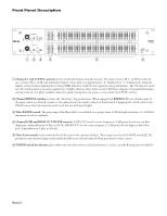
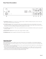
Block Diagram ME60S microGRAPHIC EQUALIZER 2 (+) 1 3 (-) CHANNEL 1 INPUTS RFI FILTER 0 dB OVERLOAD OL SENSE LEVEL -6 dB -12 dB +6 dB RANGE +12 dB LOW CUT HIGH CUT FILTER FILTER (10-250 Hz) (3k-40k Hz) CUT AMPLIFIER BOOST AMPLIFIER 25 Hz BP TO FILTERS Channel 1 is shown, channel 2 is identical. - + BYPASS SWITCH (+) 2 1 (-) 3 CHANNEL1 OUTPUTS BYPASS Constant-Q Constant-Q graphic equalizers arose from the sound professional's need for greater control with less interaction than previously possible with conventional equalizers. You use a constant-Q graphic the same way you use a conventional graphic. You just get the desired results quicker, with far less after adjustment to the adjacent sliders. The accompanying figures dramatically show the advantages of constant-Q designs. For more technical information, consult the references on the next page. Most are available at www.rane.com/library.html. AMPLITUDE AMPLITUDE Constant-Q: 3dB Proportional Q: 3dB 1/3 octave 1/3 octave 3dB 3dB 1/3+ octave Bandwidth, de ned 3dB down from peak, remains constant. 2+ octaves Bandwidth here changes dramatically with changes in gain. FREQUENCY Constant-Q: This design has little interaction as a single slider is moved from 2 1 to 2. 1 Proportional Q: Both lters are a ected when a single slider is moved from 2 1 to 2. 1 +6dB 2 +3dB 0dB 1 2 1 FREQUENCY Data Sheet-3
-
 1
1 -
2
-
3
-
4
-
 5
5 -
 6
6 -
 7
7 -
 8
8 -
 9
9 -
 10
10 -
 11
11 -
 12
12 -
 13
13 -
 14
14 -
 15
15 -
16
-
17
-
18
-
19
-
20
-
21
-
22
-
23
-
24
 |
 |
