Rane ME60S Instruction Manual - Page 5
Front Panel Description - manual
 |
View all Rane ME60S manuals
Add to My Manuals
Save this manual to your list of manuals |
Page 5 highlights
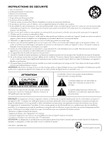
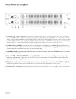
Front Panel Description 4 6 CHANNEL 1 2 8 ±12 0 10 OL LEVEL BYPASS ±6 RANGE 4 6 CHANNEL 2 2 8 ±12 0 10 OL LEVEL BYPASS ±6 RANGE LOW HIGH 250 3k 150 5k 40 10k 15 30k 10 40k CUT FILTERS 25 31.5 40 50 63 80 100 125 160 200 250 315 400 500 630 800 1k 1.25k 1.6k 2k 2.5k 3.15k 4k 5k 6.3k 8k 10k 12.5k 16k 20k 6 12 • • 3 6 • • 0 0 • • 3 6 • • 6 12 LOW HIGH 250 3k 150 5k 40 10k 15 30k 10 40k CUT FILTERS 25 31.5 40 50 63 80 100 125 160 200 250 315 400 500 630 800 1k 1.25k 1.6k 2k 2.5k 3.15k 4k 5k 6.3k 8k 10k 12.5k 16k 20k 6 12 • • 3 6 • • 0 0 • • 3 6 • • 6 12 POWER ME60S MICROGRAPHIC EQUALIZER 123 4 5 6 1 Channels 1 and 2 LEVEL controls set the overall desired gain through the unit. The range is from Off to +8 dB for balanced use, or from Off to +2 dB with unbalanced inputs. Unity gain is at approximately "6" (balanced) or "7" (unbalanced). Using the highest setting (without lighting the Overload (OL) indicator) yields the best signal-to-noise performance. The OL indicator monitors all critical points for excessive signal levels. It lights whenever these levels exceed 3 dB below clipping. Occasional flickering is normal; however, if it glows steadily, reduce the signal coming from the source, or turn down the LEVEL control. 2 Channel BYPASS switches activates the "hard-wire" bypass function. When engaged (red BYPASS LED on), all three pins of the input connectors directly connect to the same pins on the output connectors (hard-wired). Engaging this switch converts the ME60S into a relatively expensive patch cord, but one with pretty lights. 3 Filter RANGE switch: The gain range of the filter sliders is switchable (as a group) from ±6 dB for high resolution, to ±12 dB for maximum boost/cut capability. 4 Channel LOW and HIGH CUT FILTER controls. LOW CUT sets the corner frequency (-3 dB point) for the low cut filter (high pass), adjustable from 10 Hz to 250 Hz. HIGH CUT sets the corner frequency (-3 dB point) for the high cut filter (low pass), adjustable from 3 kHz to 40 kHz. 5 Filter level controls set the individual levels for each of the constant-Q filters. Their range is set by the RANGE switch 3. The grounded center-detent design ensures individual filters are off and bypassed when positioned to their centers. 6 POWER switch & indicator glows yellow any time this switch is closed and power is, in fact, actually flowing into the ME60S. Manual-2
-
 1
1 -
 2
2 -
 3
3 -
 4
4 -
 5
5 -
 6
6 -
 7
7 -
 8
8 -
 9
9 -
 10
10 -
 11
11 -
12
-
13
-
14
-
15
-
16
-
17
-
18
-
19
-
20
-
21
-
22
-
23
-
24
 |
 |
