Panasonic WU-144MF1U9E Technical and Service Data - Page 65
Solenoid Valve Kit for 3WAY VRF System, CZ-P56HR1U, CZ-P160HR1U, Recommended, installation, Avoid
 |
View all Panasonic WU-144MF1U9E manuals
Add to My Manuals
Save this manual to your list of manuals |
Page 65 highlights
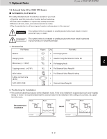
7. Optional Parts Design of 3WAY VRF SYSTEM 7-2. Solenoid Valve Kit for 3WAY VRF System CZ-P56HR1U, CZ-P160HR1U For safety installation and trouble-free operation, you must: Carefully read this instruction booklet before beginning. Follow each installation or repair step exactly as shown. Observe all local, state, and national electrical codes. Pay close attention to all warning and caution notices given in this manual. WARNING This symbol refers to a hazard or unsafe practice which can result in severe personal injury or death. CAUTION This symbol refers to a hazard or unsafe practice which can result in personal injury or product or property damage. 1. Accessories Part Name Figure Q'ty Remarks 1 Washer 2 For hanging bolts Hanging hook 1 Used to hang the Solenoid Valve Kit 2 M4 screw ( L=15/32") 4 For hanging hook Tapping screw ( L=5/16") 4 For Solenoid Valve Relay Kit Wire holder 3 1 For Solenoid Valve Relay Kit wiring 3-Way connect wire (6.5ft.) 1 ACC-3WAY-AAB 1 Solenoid Valve Relay Kit 4 2. Positioning for Installation The solenoid valve kit produces some refrigerant noise. If it is to be installed in a quiet place such as a hospital, 5 library or hotel, it is recommended that the solenoid valve kit be installed in the ceiling of a corridor, etc. apart from the room. Room Room Room Room Indoor unit Indoor unit Indoor unit Indoor unit 6 Recommended installation Avoid Solenoid valve kit Corridor Corridor Solenoid valve kit 7 8 2 - 51
-
 1
1 -
2
-
3
-
4
-
5
-
6
-
7
-
8
-
9
-
10
-
11
-
12
-
13
-
14
-
15
-
16
-
17
-
18
-
19
-
20
-
21
-
22
-
23
-
24
-
25
-
26
-
27
-
28
-
29
-
30
-
31
-
32
-
33
-
34
-
35
-
36
-
37
-
38
-
39
-
40
-
41
-
42
-
43
-
44
-
45
-
46
-
47
-
48
-
49
-
50
-
51
-
52
-
53
-
54
-
55
-
56
-
57
-
58
-
59
-
 60
60 -
 61
61 -
 62
62 -
 63
63 -
 64
64 -
 65
65 -
 66
66 -
 67
67 -
 68
68 -
 69
69 -
 70
70 -
71
-
72
-
73
-
74
-
75
-
76
-
77
-
78
-
79
-
80
-
81
-
82
-
83
-
84
-
85
-
86
-
87
-
88
-
89
-
90
-
91
-
92
-
93
-
94
-
95
-
96
-
97
-
98
-
99
-
100
-
101
-
102
-
103
-
104
-
105
-
106
-
107
-
108
-
109
-
110
-
111
-
112
-
113
-
114
-
115
-
116
-
117
-
118
 |
 |
