Panasonic WU-144MF1U9E Technical and Service Data - Page 52
Prepare the Tubing
 |
View all Panasonic WU-144MF1U9E manuals
Add to My Manuals
Save this manual to your list of manuals |
Page 52 highlights
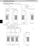
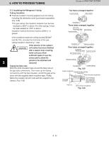
4. Installation Instructions Design of 3WAY VRF SYSTEM 4-12. Prepare the Tubing Material: Use C1220 phosphorous deoxidized copper as described in JIS H3300, "Copper and Copper Alloy Seamless Pipes and Tubes." (For tubes that are ø1" (ø25.4 mm) or larger, use 1/2H material or H material. For all others use O material.) Tubing size Use the tubing size indicated in the table below. When cutting the tubing, use a tube cutter, and be sure to remove any burrs. (The same applies to distribution tubing (optional).) When bending the tubes, bend each tube using a radius that is at least 4 times the outer diameter of the tube. When bending, use sufficient care to avoid crushing or damaging the tube. For flaring, use a flare tool, and be sure that flaring is performed correctly. CAUTION Use sufficient caution during preparation of the tubing. Seal the tube ends by means of caps or taping to prevent dust, moisture, or other foreign substances from entering the tubes. Refrigerant tubing (Existing tubing can be used.) Tubing size (mm) 1 Outer dia. ø1/4" (ø6.35) Thickness t1/32" (t0.8) Outer dia. ø3/4" (ø19.05) Thickness over t5/128" (t1.0) ø3/8" (ø9.52) t1/32" (t0.8) ø7/8" (ø22.22) t5/128" (t1.0) ø1/2" (ø12.7) t1/32" (t0.8) ø1-1/8" (ø28.58) t5/128" (t1.0) ø5/8" (ø15.88) t5/128" (t1.0) ø1-3/8" (ø34.92) over t3/64" (t1.1) 2 4-13. Connect the Tubing Use the supplied connector tubing. (See figure below.) 72 type (6-Ton) 3 43 21 Refrigerant tubing Connection method Use supplied connector tube? 4 1 Suction tube Brazed connection No 2 Discharge tube Brazed connection No 3 Liquid tube Brazed connection No 4 Balance tube Flared connection No 5 96 type (8-Ton) 43 21 6 Refrigerant tubing Connection method Use supplied connector tube? 1 Suction tube Brazed connection Yes (ø3/4" ψ ø7/8") 2 Discharge tube Brazed connection Yes (ø5/8" ψ ø3/4") 3 Liquid tube Brazed connection No 7 4 Balance tube Flared connection No Refrigerant tube port Use caulking, putty, or a similar material to fill any gaps at the refrigerant tube port ( ) in order to 8 prevent rainwater, dust or foreign substances from entering the unit. Tubing cover Base plate * Perform this work even if the tubing is routed out in a downward direction. Tubing routed out forward Tubing routed out downward 2 - 38
-
 1
1 -
2
-
3
-
4
-
5
-
6
-
7
-
8
-
9
-
10
-
11
-
12
-
13
-
14
-
15
-
16
-
17
-
18
-
19
-
20
-
21
-
22
-
23
-
24
-
25
-
26
-
27
-
28
-
29
-
30
-
31
-
32
-
33
-
34
-
35
-
36
-
37
-
38
-
39
-
40
-
41
-
42
-
43
-
44
-
45
-
46
-
 47
47 -
 48
48 -
 49
49 -
 50
50 -
 51
51 -
 52
52 -
 53
53 -
 54
54 -
 55
55 -
 56
56 -
 57
57 -
58
-
59
-
60
-
61
-
62
-
63
-
64
-
65
-
66
-
67
-
68
-
69
-
70
-
71
-
72
-
73
-
74
-
75
-
76
-
77
-
78
-
79
-
80
-
81
-
82
-
83
-
84
-
85
-
86
-
87
-
88
-
89
-
90
-
91
-
92
-
93
-
94
-
95
-
96
-
97
-
98
-
99
-
100
-
101
-
102
-
103
-
104
-
105
-
106
-
107
-
108
-
109
-
110
-
111
-
112
-
113
-
114
-
115
-
116
-
117
-
118
 |
 |
