Panasonic WU-144MF1U9E Service Manual - Page 19
Possible cause of malfunction, Alarm, Message
 |
View all Panasonic WU-144MF1U9E manuals
Add to My Manuals
Save this manual to your list of manuals |
Page 19 highlights
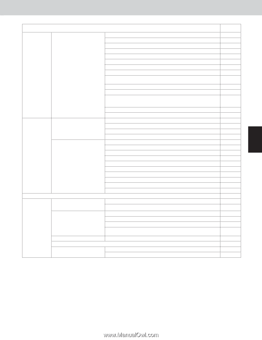
6. Meaning of Alarm Messages Test Run Possible cause of malfunction Alarm Message Activation of protective device Protective device in indoor unit is activated. Thermal protector in indoor unit fan motor is activated. Improper wiring connections of ceiling panel. Float switch is activated. Operation of protective function of fan inverter. P12 O2 sensor (detects low oxygen level) activated. P14 Incorrect discharge temperature. (Comp. No. 1 (INV)) P03 High pressure switch is activated. P04 Negtive (defective) phase. P05 Compressor running failure resulting from missing phase in the compressor wiring, etc. (Start failure not caused by IPM or no gas.) P16 Incorrect discharge temperature. (Comp. No. 2 (constant speed)) P17 Outdoor unit fan motor is unusual. P22 Overcurrent at time of compressor runs more than 80Hz (DCCT secondary current or ACCT primary current is detected at a time other P26 than when IPM has tripped.) IPM trip (IPM current or temperature) H31 Inverter for compressor is unusual. (DC compressor does not operate.) P29 Thermistor fault Indoor thermistor is either open Indoor coil temp. sensor (E1) or damaged. Indoor coil temp. sensor (E3) Indoor suction air (room) temp. sensor (TA) Outdoor thermistor is either Indoor discharge air temp. sensor (BL) Comp. No. 1 (INV) discharge gas temp. sensor (DISCH1) F04 1 open or damaged. Comp. No. 2 (constant speed) discharge gas temp. sensor (DISCH2) F05 Outdoor No. 1 coil gas temp. sensor (EXG1) F06 Outdoor No. 1 coil liquid temp. sensor (EXL1) F07 Outdoor air temp. sensor (AIR TEMP) Compressor suction temp. sensor (SCT) F08 F12 2 High pressure sensor. F16 Low-pressure sensor failure F17 Outdoor No. 2 coil gas temp. sensor (EXG2) F23 EEPROM on indoor unit PCB failure Protective device for compressor is activated Protective device for compressor No.1 (INV) is activated. Protective device for compressor No.2 (constant speed) is activated Outdoor No. 2 coil liquid temp. sensor (EXL2) EEPROM on the main or sub outdoor unit PCB has failed. Current is not detected when comp. No. 1 (INV) is ON. Overload current is detected. Lock current is detected. Current is not detected when comp. No.2 (constant speed) is ON. Discharge gas temperture of comp. No.2 (constant speed) is not detected. F24 F29 3 F31 H03 H11 H12 H13 4 H15 Low pressure trouble H06 Low oil level alarm. H07 Oil sensor fault. (Disconnection, etc.) Comp. No.1 (INV) oil sensor Comp. No.2 (constant speed) oil sensor H08 H27 5 Continued 6 7 1 - 15
-
 1
1 -
2
-
3
-
4
-
5
-
6
-
7
-
8
-
9
-
10
-
11
-
12
-
13
-
 14
14 -
 15
15 -
 16
16 -
 17
17 -
 18
18 -
 19
19 -
 20
20 -
 21
21 -
 22
22 -
 23
23 -
 24
24 -
25
-
26
-
27
-
28
-
29
-
30
-
31
-
32
-
33
-
34
-
35
-
36
-
37
-
38
-
39
-
40
-
41
-
42
-
43
-
44
-
45
-
46
-
47
-
48
-
49
-
50
-
51
-
52
-
53
-
54
-
55
-
56
-
57
-
58
-
59
-
60
-
61
-
62
-
63
-
64
-
65
-
66
-
67
-
68
-
69
-
70
-
71
-
72
-
73
-
74
-
75
-
76
-
77
-
78
-
79
-
80
-
81
-
82
-
83
-
84
-
85
-
86
-
87
-
88
-
89
-
90
-
91
-
92
-
93
-
94
-
95
-
96
-
97
-
98
-
99
-
100
-
101
-
102
-
103
-
104
-
105
-
106
-
107
-
108
-
109
-
110
-
111
-
112
-
113
-
114
-
115
-
116
-
117
-
118
-
119
-
120
-
121
-
122
-
123
-
124
-
125
-
126
-
127
-
128
 |
 |